Example 15.2 The physicals and calculated frequencies for the Machine Faults Simulator (MFS) pillow block bearings (MB ER-10K) are as follows: (i) quantity of rolling elements Z: eight (8) balls, (ii) ball diameter (Db): 0.3125 inch, (iii) pitch diameter (Dm): 1.319 inch and (iv) contact angle![]() : 0 degree.
: 0 degree.
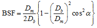
Solution: To calculate the BPFO multiplier, the following formula is used:
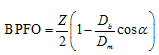
To calculate the BPFI multiplier, the following formula is used:
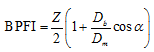
To calculate the BSF multiplier, the following formula is used:
To calculate the FTF multiplier, the following formula is used:
![]()
On putting the parameters into the above formulas we get the different faults frequency multipliers as listed in Table 15.1.

The machine –fault simulator was configured to eliminate all defects, and good bearing was installed in both the bearing housing with and without the bearing loader and baseline data was collected. The bearing loader was installed center hung adjacent to the outboard bearing. Baseline data was collected at several speeds (10Hz, 20Hz, 30Hz).
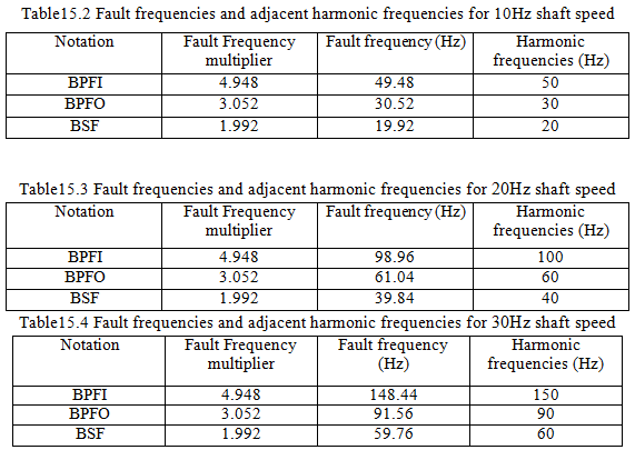
After that the defective bearing was then installed in the outboard position. Data were collected at similar speeds as previously. Baseline measurements were compared with the vibration signatures of the defective bearings. Tables 15.2-15.4 illustrate the trends of fault frequencies and adjacent harmonic frequencies at different rotational speeds.
Table15.2 Fault frequencies and adjacent harmonic frequencies for 10Hz shaft speed
Figures 15.12-15.15 illustrates of typical frequency spectra showing the inner race fault, outer race fault, rolling element fault and combination fault at the shaft running speed of 10Hz. In these figures the vibration data collected from the sensor was placed at the bearing housing in the vertical direction. In the spectra, the harmonics of running frequency as well as the fault frequency was also appeared.