Isometric axes can be positioned in a number of ways to create different views of the same object. Figure 6(a) is a regular isometric, in which the viewpoint is looking down on the top of the object. In a regular isometric, the axes at 30° to the horizontal are drawn upward from the horizontal. In the reversed axis isometric, as shown in figure 6(b), the viewpoint is looking up on the bottom of the object, and the 30° axes are drawn downward from the horizontal. Figure 6(c)&(d) show the long axis isometric, where the viewpoint is looking from the right or from the left of the object, and one axis is drawn at 60 ° to the horizontal. While drawing the Isometric view, first the view point will have to be decided for obtaining the maximum technical information.
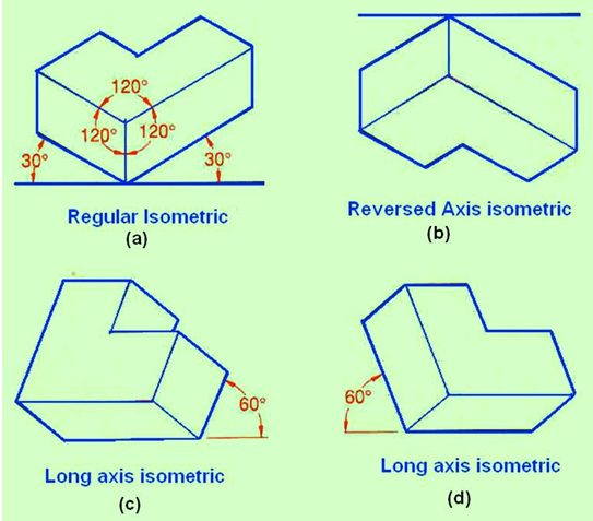
Figure 6. shows different isometric axis depending on the direction of view point.
Isometric axes and non-isometric axes
Figure 7(a) illustrates the isometric axes, non-isometric axes and isometric planes. In an isometric drawing, true length distances can only be measured along isometric lines. i.e. lines that run parallel to any of the isometric axes. Any line that does not run parallel to an isometric axis is called a non-isometric line. Non-isometric lines include inclined and oblique lines and cannot be measured directly. Instead they must be created by locating two end points. Figure 7(b) is an isometric drawing of a cube. The three faces of the isometric cube are isometric planes, because they are parallel to the isometric surfaces formed by any two adjacent isometric axes. Planes that are not parallel to any isometric plane are called non-isometric planes sa shown in figure 7(a).
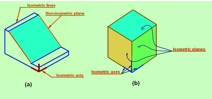
Figure 7. showing isometric axes, non-isometric axes and isometric planes.