Isometric Axonometric Projections
An isometric projection is a true representation of the isometric view of an object. An isometric view of an object is created by rotating the object 45° about a vertical axis, then tilting the object (see figure 3, in this case, a cube) forward until the body diagonal (AB) appears as a point in the front view. The angle the cube is tilted forward is 35° 16’. The 3 axes that meet at A, B form equal angles of 120° and are called the isometric axes. Each edge of the cube is parallel to one of the isometric axes. Line parallel to one of the legs of the isometric axis is an isometric line. Planes of the cube faces & all planes parallel to them are isometric planes
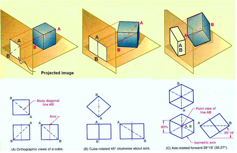
Figure 3. Rotation of the object with respect to the projection plane result in isometric projection.
The forward tilt of the cube causes the edges and planes of the cube to become shortened as it is projected onto the picture plane. The lengths of the projected lines are equal to the cosine of 35° 16’, or 0.81647 times the true length. In other words, the projected lengths are approximately 80% of the true lengths. A drawing produced using a scale of 0.816 is called an isometric projection and is a true representation of the object. However, if the drawing is produced using full scale, it is called an isometric drawing, which is the same proportion as an isometric projection, but is larger by a factor of 1.23 to 1. Figure 4. Illustrates the isometric projection and isometric drawing. Isometric drawings are almost always preferred over isometric projection for engineering drawings, because they are easier to produce. An isometric drawing is an axonometric pictorial drawing for which the angle between each axis equals 120° and the scale used is full scale.