Intersection of Cylinder and Cylinder
The line of intersection between cylinders will be curved since the lateral surfaces of cylinders are curved. Points on the intersection line can be located by either line method or cutting plane method. For plotting an accurate curve, the points at which the curve changes direction must also be located. These points lie on the outermost or extreme lines of each cylinder pierce the surface of the other cylinder. For obtaining the intersection of cylinder and cylinder, cutting plane method is more useful. In this technique, a series of horizontal cutting planes are assumed to be passing through the lines of the horizontal cylinder and these planes cuts both cylinders as shown in figure 3. After each sectioning, the top view of the section of the horizontal cylinder will be a rectangle with its width depending on the position of the cutting plane, where as the top view of the vertical cylinder will be a circle with diameter equal the diameter of the vertical cylinder. The points at which the sides of the rectangles intersect the circle will lie on the curve of intersection. The procedure is illustrated through problem 2.
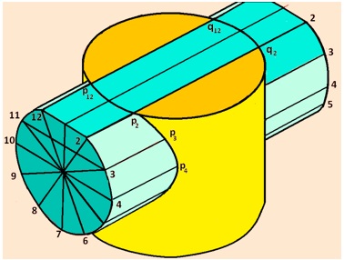
Figure 3 illustrating the cutting plane method for obtaining the curve of intersection.
Problem 2
A vertical cylinder of 80 mm diameter is completely penetrated by another cylinder of 60 mm diameter, their axes bisecting each other at right angles. Draw their projections showing curves of penetration, assuming the axis of the penetrating cylinder to be parallel to the VP.
Solution:
The solution is shown in figure 3. The Front view, top view and side view of the two cylinders are drawn with out the intersection lines. Divide the circumference of the circle in the side view in to 12 equal parts. Draw horizontal projectors from these points on to the front view. Project the same points from the side view on to the top view and obtain lines 1-1, 2-2, 3-3 , etc. Let us now consider a horizontal sectio plane passing through points 2-2 and 12-12 (shown in figure 3).
In the front view, it will be seen as a line coinciding with line 2’ 2'. In the top view, the section of the horizontal cylinder will be a rectangle of width (i.e. the line 2-12). The section of the vertical cylinder will be a circle. Points p2 and p12 at which the sides (2-2 and 12-12) of the rectangle cuts the circle will lie on the curve of intersection. This point is first obtained in the top view by the intersecting point of line 12-12 and 2-2 with the circle. Vertical projector lines are drawn from these points to the front view so as to intersect with the horizontal projectors drawn through points 2 and 12 in the side view to obtain P2’ and P12’ in the front view.
Other cutting planes are also assumed passing through 3-11, 4-10, etc and the procedure repeated to obtain other points p3’, p4’, p5’, etc. Similar procedure is adopted to obtain points q1’, q2’, etc on the right hand side. Since the axis to the two cylinders intersect, points p2’ and p12’ will coincide and hence cannot be shown in the figure.
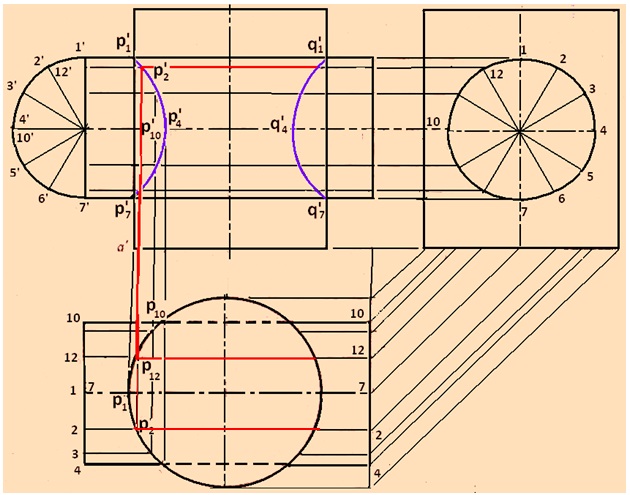
Figure 4. solution to problem 2.