Intersection of solids
Whenever two or more solids combine, a definite curve is seen at their intersection. This curve is called the curve of intersection (COI). Lines of intersection are a common feature in engineering applications or products. Figure 1 shows few examples of intersection lines frequently observed in chemical plants, domestic appliances, pipe joints, etc. Curves of intersections are important from the point of view of production of components for engineering applications.
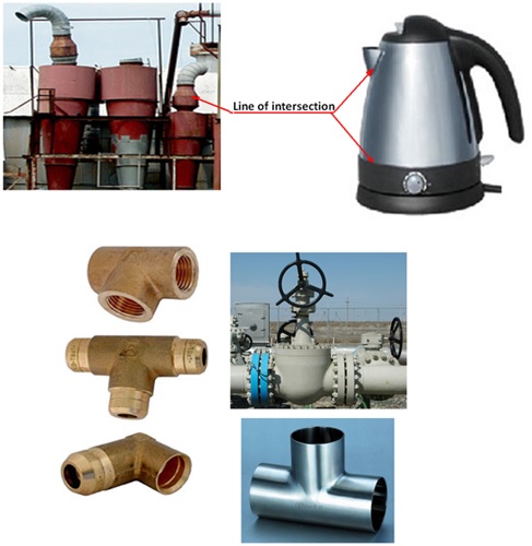
Figure 1. photographs of engineering components showing cures of intersection.
Cases of Intersection
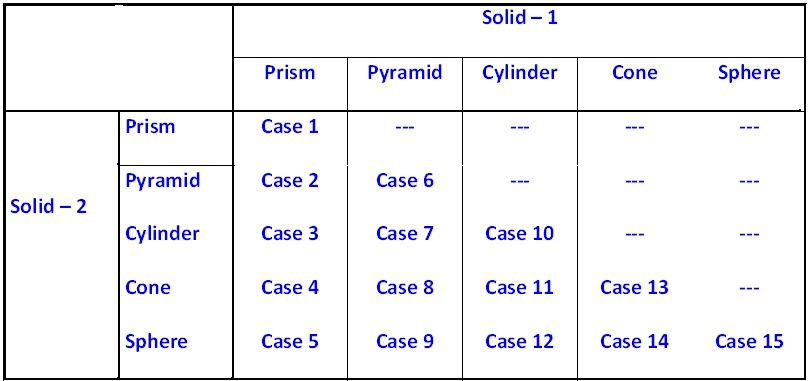
The cases of intersection depend on the type of intersecting solids and the manner in which they intersect. Two intersecting solids may be of the same type (e.g., prism and prism) or of different types (e.g., prism and pyramid). The possible combinations are shown in table 1.:
Table 1. Different cases of intersection
The two solids may intersect in different ways. The axes of the solids may be parallel, inclined or perpendicular to each other. The axes may be intersecting, offset or coinciding. Therefore, the following sub-cases exist:
(i) Axes perpendicular and intersecting
(ii) Axes perpendicular and offset
(iii) Axes inclined and intersecting
(iv) Axes inclined and offset
(v) Axes parallel and coinciding
(vi) Axes parallel and offset
The type of intersection created depends on the types of geometric forms, which can be two- or three- dimensional. Intersections must be represented on multiview drawings correctly and clearly. For example, when a conical and a cylindrical shape intersect, the type of intersection that occurs depends on their sizes and on the angle of intersection relative to their axes as well as relative position of their axes.
The line of intersection is determined using auxiliary views and cutting planes.
Methods – (1) Line and (2) Cutting-plane methods