Line method:A number of lines are drawn on the lateral surface of one of the solids and in the region of the line of intersection. Points of intersection of these lines with the surface of the other solid are then located. These points will lie on the required line of intersection. They are more easily located from the view in which the lateral surface of the second solid appears edgewise (i.e. as a line). The curve drawn through these points will be the line of intersection.
Cutting-plane method: The two solids are assumed to be cut by a series of cutting planes. The cutting planes may be vertical (i.e. perpendicular to the H.P.), edgewise (i.e. perpendicular to the V.P.) or oblique. The cutting planes are so selected as to cut the surface of one of the solids in straight lines and that of the other in straight lines or circles.
Intersection of two prisms
Prisms have plane surfaces as their faces. The line of intersection between two plane surfaces is obtained by locating the positions of points at which the edges of one surface intersect the other surface and then joining the points by a straight line. These points are called vertices. The line of intersection between two prisms is therefore a closed figure composed of a number of such lines meeting at the vertices. The method of obtaining intersection lines are shown by means of problem.
Problem 1. A vertical square prism, base 50 mm side, is completely penetrated by a horizontal square prism, base 35 mm side, so that their axes intersect. The axis of the horizontal prism is parallel to the prism, while the faces of the two prisms are equally inclined to the prism. Draw the projections of the solids, showing lines of intersection. (Assume suitable lengths for the prisms.)
Solution
The intersection obtained is shown in figure 2. Draw the projections of the prisms in the required position. The faces of the vertical prism are seen as lines in the top view. The points of intersection in this view can be located by the following method.
Lines 1-1 and 3-3 intersect the edge of the vertical prism at points p1 and p3 (coinciding with a). Lines 2-2 and 4-4 intersect the faces at p2 and p4 respectively. The exact positions of these points along the length of the prism may now be determined by projecting them on corresponding lines in the front view. For example, p2 is projected to p2' on the line 2'2'. Note that p4' coincides with p2'. Similarly other points are obtained. Draw lines p1’p2' and p2‘p3'. Lines p1‘p4' and p3‘p4' coincide with the front lines. These lines show the line of intersection. Lines q1'q2' and q2‘q3' on the other side are obtained in the same manner. Note that the lines for the hidden portion of the edges are shown as dashed lines. The green lines in the figure represents construction lines. The portions p1’p3' and q1’q3' of vertical edges a'a' and c'c' do not exist and hence, must be removed or kept fainter.
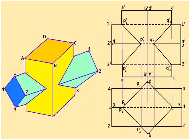
Figure 2 The lines of intersection obtained for problem 1.