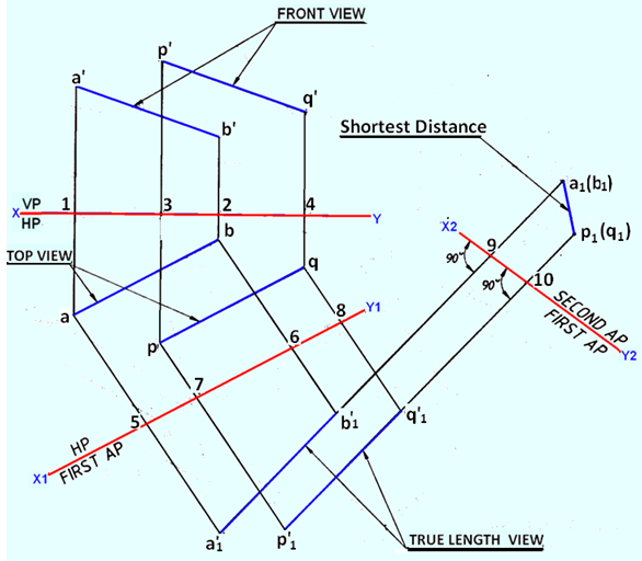
Figure 6. Determination of shortest distance between two parallel lines.
Draw the X1Y1 line parallel to ab and pq at any convenient distance from them.
Through the points a, b, p and q, draw projector lines perpendicular to X1Y1 line.
Measure 5a1’=1a1’ along the projector drawn through a from the X1Y1 line, and 6b1’=2b’ along the projector drawn through b from the X1Y1 line.
Connect a1'b1' which will be equal to the true length of the line AB.
Similarly by measuring 7p1'= 3p' and 8q1' = 4q' obtain p1'q1' the true length view of the line PQ.
The line AB and PQare shown in their true lengths, and now an another auxiliary plane perpendicular to the two given lines should be set up to project their point views on it.
Draw the line X2Y2 perpendicular to a1’b1' and p1'q1' at any convenient distance from them.
Produce a1'b1' and p1'q1'.
Measure a5 = b6 = 9a1along a1'b1' produced from X2Y2. Similarly obtain the point,view p1(q1) by measuring p1(10)=p7 = q8.
Connect p1a1 the required shortest distance between the lines AB and PQ in its true length .
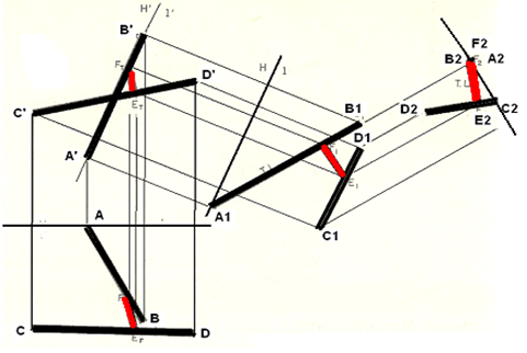
Shortest distance between two skew lines
Projections of two skew lines AB and CD are shown as A’B’, C’D’ and AB and CD.
Determine the shortest distance EF between the line segments
First an Auxiliary A1B1 is made showing the true length of AB.
A second auxiliary view showing the point view of AB is projected.
For this draw the reference line normal to A1B1 and draw the projectors C2 D2 (of C1 and D1).
The shortest distance F2E2 can be established perpendicular to CD.
To project FE back to the Front and Top Views, FE is first projected in first auxiliary plane by first projecting point E, which is on CD, from the second to the first auxiliary view and then back to the front and top views.