Projection of lines by auxiliary plane method
The problems on projection of lines inclined to both the planes may also be solved by the auxiliary plane methods.
In this method, the line is always placed parallel to both HP and VP, and then two auxiliary planes are set up: one auxiliary plane will be perpendicular to VP and inclined at q to HP, i.e., AIP, and the other will be perpendicular to HP and inclined at f (true inclination) or b (apparent inclination) to VP. Projection of lines by auxiliary plane method are illustrated by problems shown below:
Problem 1:
Draw the projections of a line 80 mm long inclined at 300 to HP and its top view appears to be inclined at 600 to VP. One of the ends of the line is 45 mm above HP and 60 mm in front of VP. Draw its projections by auxiliary plane method
Solution
Draw the top and front views of one of the ends, say A, 45 mm above HP and 60 mm in front of VP.
Assume that the line is parallel to both HP and VP and draw its top and front views as shown in figure 1.
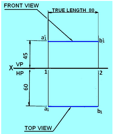
Figure 1. The FV and TV of the line AB when parallel to HP and VP
Since the line is to be inclined at 300 to HP, set up an AIP inclined at 300 to HP and perpendicular to VP.
Draw X1Y1 line inclined at 300 to XY line at any convenient distance from it as shown in figure 2.
To project an auxiliary top view on AIP, draw projections from a1’ and b1’ perpendicular to X1Y1 line, and on them step off 1a1=3a and 2b1=4b from the X1Y1 line.
Connect ab which will be the auxiliary top view.
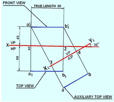
Figure 2. Projection of line on to the AIP.
Since the top view of the line appears inclined to VP at 600, draw the X2Y2 line inclined at 600 to the auxiliary
top view ab at any convenient distance from it as shown in figure 3. Draw the projections from a and b perpendicular to X2Y2 and
on them step off 5a’ = 3a1’and 6b’=4b1’. Connect a’b’ which will be the auxiliary front view.
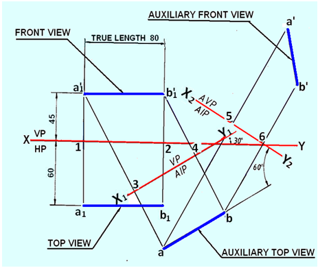
Figure 3. Auxiliary front view of the the line Ab.