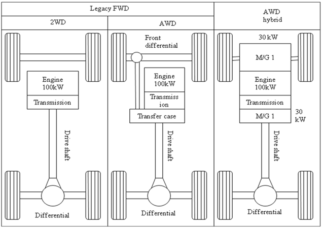
Fig.4. AWD hybrid design starting with an RWD legacy vehicle. The three drawings are 2WD, the conventional AWD, and hybrid AWD.
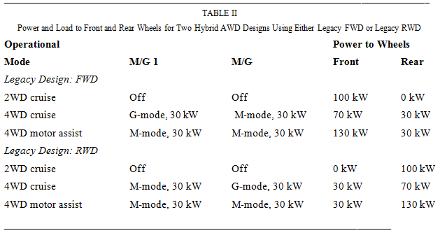
Table I, which is coordinated with Figure3 and 4 , shows the front and rear power loading for legacy FWD and legacy RWD. The traction motors are limited in power due to battery limitations. For discussion purposes, each M/G has a realistic 30 kW and the engine is 100 kW.
In motor assist, the battery must supply 60 kW, which is 30 kW for each M/G in M-mode (Figure 3). With a legacy FWD, the M/G is on the rear axle. This means the traction load on the rear axle is limited to 30 kW (Figure 3). With a legacy RWD, the M/G is on the front axle. This means the traction load on the front axle is limited to 30 kW, which is favorable in regard to loading of the tires.
Figure 3 shows a legacy design of FWD for the optional 2WD. When the 2WD version of unmodified vehicle is FWD, then a hybrid conversion will undoubtedly have an electric traction motor driving the rear wheels. Front/rear torque bias will likely be reversed 70/30 F/R, which is usually unfavorable.
Figure 4 shows a legacy design of RWD for the optional 2WD. If the 2WD version of the unmodified vehicle is RWD, then a hybrid conversion will undoubtedly have electric traction motor driving the front wheels. Front/rear torque bias will likely be a favorable 30/70 F/R.
AWD hybrid vehicles operate in the 2WD cruise mode of Table II. In the motor assist mode, both M/G are in M-mode providing traction. Hence
H = 60kW / (100 + 60kW) = 37.5%
References:
[1] A. E. Fuhs, Hybrid Vehicles and the Future of Personal Transportation , CRC Press, 2009