Constant Mutual Flux Linkage Control
In this control strategy, the resultant flux linkage of the stator q and d axis and rotor is maintained constant. The main advantage of this control strategy is that it keeps the stator voltage requirement is kept low. To start with the analyses consider the flux linkage expression (Lecture 24, equations 32 and 33) for the q and d axis:
|
(15) (16) |
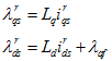
The magnitude of the flux linkage is given by
|
(17) |
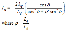
In this strategy, the mutual flux linkage given by equation 17 is held constant and its magnitude is made equal to λaf. Substituting the values of ![]() from equation 2 into equation 17 gives
from equation 2 into equation 17 gives
|
(18) |
Solving equation 18 for Im gives
|
(19) |
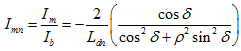
The normalized current is given bu
|
(20) |
The stator voltage is given
|
(21) |
The normalized values of the stator voltage is
|
(22) |
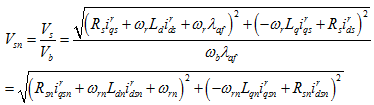
Using equation 2, the normalized voltage given by equation 25 can be written as
|
(23) |
In order to determine the value of angle δ, two distinct cases have to be considered: when ρ = 1 and ρ ≠ 1. Once the angle δ is known, the torque can be obtained from equation 3.
Each of these cases are explained in the following subsections.
Case when ρ = 1
Substituting ρ = 1 into equation 20 and solving for δ gives
|
(24) |
The torque produced by the machine is given by
|
(25) |
The normalized torque is given by
|
(26) |
The performance characteristics of a PM machine at a speed of 1 p.u. are shown in Figure 4a and the parameters of this machine are given in Table 2. The torque versus the speed characteristics of the PM Machine are shown in Figure 4b.