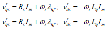
From equation 8 it can be seen that the normalized torque (Ten) is equal to the normalized stator current Isn. The voltage equation for steady state analysis can be obtained by making p = 0 (because in steady state the time variation is zero) in equation 6 and is written as
 |
(9) |
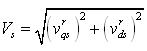
The magnitude of the stator voltage is given by
 |
(10) |
The normalized stator voltage is obtained as
|
(11) |
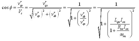
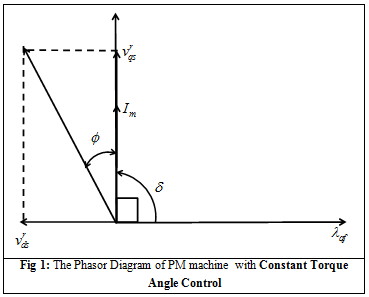
The phasor diagram for this control strategy is shown in Figure 1. From this figure the power factor is obtained as
|
(12) |
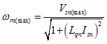
The equation 12 shows that the power factor deteriorates as the rotor speed goes up. The maximum rotor speed with this control strategy can be obtained by solving equation 11 for ωm, neglecting the stator resistive drop (RsnImn ≈ 0), and is given as
|
(13) |
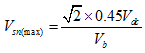
Assuming that the motor is driven by a three phase DC-AC converter, the maximum voltage is given by (refer Lecture 15):
|
(14) |
The performance characteristics of the PM machine are shown in Figure 2. The parameters of the machine for a speed of 1p.u. (ωm = 1) used to plot the curves are given in Table 1. From the Figure 2 the following can be observed:
- The power factor falls as the current rises.
- The torque is proportional to the current as is evident from equation 8 .
- The normalized increases with the increase in current. The impedance of the machine remains constant because its speed is constant at 1p.u. hence, when the current through the machine has to increase the applied voltage also has to increase ( equation 11 ).
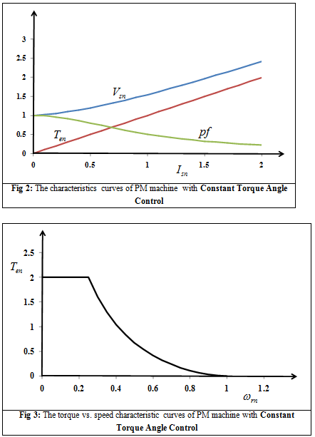
Table 1: The parameters of a salient pole PM machine
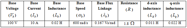
The torque vs. speed curve for the machine, whose parameters are given in Table 1, is shown in Figure 3. In determining the curve it has been assumed that the magnitude of the normalized stator voltage (Vsn) is 1 p.u. and the maximum value of normalized stator current (Imn) is fixed to 2 p.u. From the Figure 3 the following can be observed:
- Through this control strategy, the PM machine is able to produce 2 p.u. torque up to a speed of 0.25 p.u.
- The machine is able to produce 1 p.u. torque up to a speed of 0.4 p.u.