Single Phase Bridge DC-AC Inverter with R-L Load
The function of the inverter in case of R-L load can be explained as follows:
Case 1 : At time t = T1, the switches S1 and S2 are turned off and the pair of swithces S3 and S4 are turned on . Due to the inductive load, the current through the load (iL) will not change its direction at t = T1 and will continue to flow through the load from point a to b , through the diodes D3 and D4, till it becomes zero as shown in Figure 10a . Once iL = 0 , S3 and S4 start conducting and the load current iL builds up in opposite direction (point b to a ).
Case 2 : At time t = T2, the switches S1 and S2 are turned on and the pair of swithces S3 and S4 are turned off . Just as in case 1 , the current takes time to become zero and diodes D1 and D2 conduct as long as its non-zero . This condition is shown in Figure 10b .
The instantaneous current through the R-L load is given by
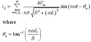 (15)
(15)
The current and voltage waveforms for R-L load are shown in Figure 11 .In this figure the conduction is didvided into 4 distinct zones. In Zone I the diode D1 and D2 conduct until iL becomes zero. Once iL equals zero , the switches S1 and S2 conduct and it is marked as Zone II . At time t = T2, the didoes D3 and D4 conduct and this is marked as Zone III in Figure 11 . Finally, in Zone IV the switches S3 and S4 conduct.