Single Phase Bridge DC-AC Inverter with R Load
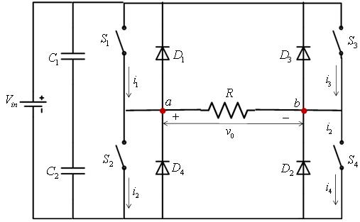
A single phase bridge DC-AC inverter is shown in Figure 8. The analysis of the single phase DC-AC inverters is done taking into account following assumptions and conventions:
- • The current entering node a in Figure 8 is considered to be positive.
• The switches S1, S2, S3, and S4 are unidirectional, i.e. they conduct current in one direction.
When the switches S1 and S2 are turned on simultaneously for a duration  , the input voltage Vin appears across the load and the current flows from point a to b . If the switches S3 and S4 are turned on for a duration
  , the voltage across the load is reversed and the current through the load flows from point b to a . The voltage and current waveforms across the resistive load are shown in Figure 9 . The instantaneous output voltage can be expressed in Fourier series as
 (11)
(11)
Due to the square wave symmetry along the x-axis (as seen in Figure 9 ), both ao and an are zero , and bn is obtained as
 (12)
(12)
Substituting the value of bn from equation 12 into equation 11 gives
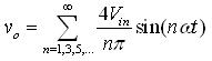 (13)
(13)
The instantaneous current through the resistive load is given by
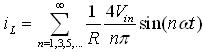 (14)
(14)
|
Figure 8 : Full bridge DC-AC inverter with resistive load |