Introduction
The topics covered in this chapter are as follows:
- • DC-AC Converters
• Principle of Operation of Half Bridge DC-AC Inverter (R Load)
• Half Bridge DC-AC Inverter with L Load and R-L Load
• Single Phase Bridge DC-AC Inverter with R Load
• Single Phase Bridge DC-AC Inverter with R-L Load
DC-AC Converters
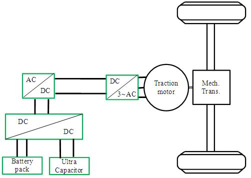
In Figure 1 a configuration of an EV. In this figure it can be seen that the traction motor requires AC input. The main source of electrical power is the battery which is a DC source. The DC output of the battery is bucked or bossted according to the requirement and then converted into AC using a DC-AC inverter . The function of an inverter is to change a dc input voltage to a symmetric ac output voltage of desired magnitude and frequency. The output voltage waveforms of ideal inverters should be sinusoidal. However, the waveforms of practical inverters are non-sinusoidal and contain certain harmonics.
|
|
|
Principle of Operation of Half Bridge DC-AC Inverter (R Load)
A single phase inverter is shown in Figure 2 . The analysis of the DC-AC inverters is done taking into account following assumptions and conventions:
- • The current entering node a in Figure 2 is considered to be positive.
• The switches S1 and S2 are unidirectional, i.e. they conduct current in one direction.
• The current through S1 is denoted as i1 and the current through S2 is i2.
The switching sequence is so design ( Figure 3 ) that switch S1 is on for the time duration  and the switch S2 is on for the time duration
  . When switch S1 is turned on, the instantaneous voltage across the load is
 (1)
(1)