|
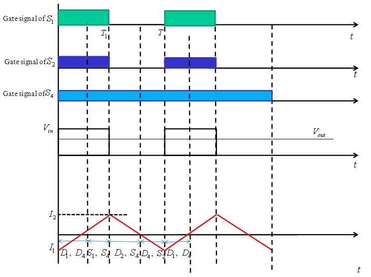
Figure 4: Waveforms for sequence 1 |
Sequence 2Operation
In this sequence, the converter operates in third and fourth quadrant and the switch S3 is permanently kept on . The switches S1 and S2 are controlled as per the following four steps:
- • Mode 1: S2 is turned on at t = 0 but starts conduction only when the current changes sign. The diodes D2 and D3 conduct (Figure 5a) till the current changes itrs sign. The instantaneous output voltage across the load is
 .
.
• Mode 2: When S2 is turned off at ![]() , the inductor continuous to drive the current in the reverse direction through S3 and D1 ( Figure 5b ).
, the inductor continuous to drive the current in the reverse direction through S3 and D1 ( Figure 5b ).
• Mode 3: The switch S1 is turned on at ![]() but does not conduct because the current flows in the negative direction and D1 and S3 conduct. Once the current changes the sign S1 and D3 conduct D1 (Figure 5c).
but does not conduct because the current flows in the negative direction and D1 and S3 conduct. Once the current changes the sign S1 and D3 conduct D1 (Figure 5c).
• Mode 4: When S1 is turned off at t = T , ![]() but positive current flows, hence, D2 and D3 conduct D1 ( Figure 5d ).
but positive current flows, hence, D2 and D3 conduct D1 ( Figure 5d ).