Four Quadrant Converter
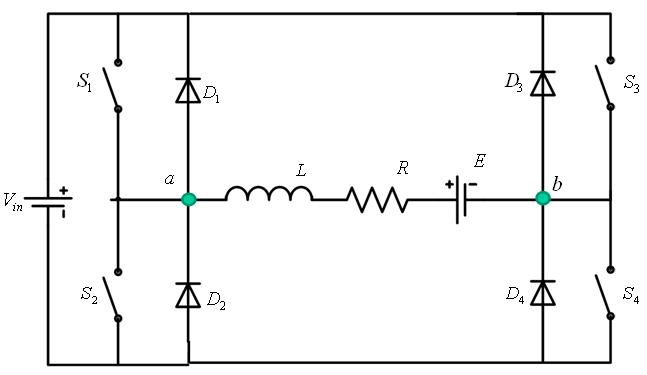
A four quadrant converter is shown in Figure 2 . The circuit is operated as a two quadrant converter to obtain:
- a) Sequence 1: First and second quadrant operation
b) Sequence 2: Third and fourth quadrant operation
|
Figure 2: Four quadrant converter |
Sequence 1 Operation
In this mode S4 is kept permanently on . The switches S1 and S2 are controlled as per the following four steps:
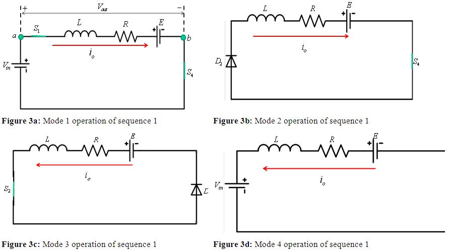
- • Mode 1: If S1 and S4 are turned on , the input voltage Vin is applied across the load and current flows in the positve direction from a to b Figure 3a . The instantaneous output voltage across the load is
 .
.
• Mode 2: When S1 is turned off at time ![]() , the current due to the stored
, the current due to the stored ![]() energy of the inductor L drives through D2 and S4 as shown in Figure 3b . The switch S2 is turned on at
energy of the inductor L drives through D2 and S4 as shown in Figure 3b . The switch S2 is turned on at ![]() but it doesnot conduct because it is shorted by D2.
but it doesnot conduct because it is shorted by D2.
• Mode 3: The switch S2 conducts when the cureent reverses its direction (Figure 3c).
• Mode 4: Finally when S2 is turned off at t = T , current flows in the negative direction (Figure 3d). The converter operates in the fourth quadrant and the power flows from load to source.
The wavforms for sequence 1 are shown in Figure 4 .