Introduction
The following topics are covered in this lecture:
• First and Second Quadrant Converter
• Four Quadrant Chopper
First and Fourth Quadrant Converter
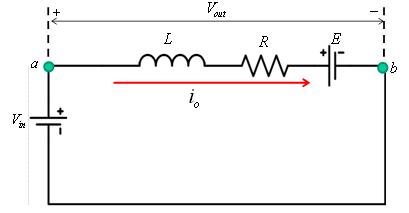
In Figure 1a the configuration of two quandrant converter capable of operating in first and fourth quadrants is shown. Both the switches S1 and S2 are turned on for a duration t = 0 to t = T1(Figure 1b) and off for a duration t = T1 to t = T . The instantaneous output voltage appearing across the load ![]() is:
is:
![]() (1)
(1)
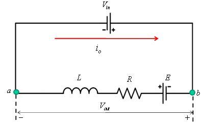
When the switches S1 and S2 are turned off , the current throught the inductor L continues to flow in the same direction, making the diodes D1 and D2 conduct thus feeding the load energy back to the dc source (Figure 1c). The average load voltage ![]() is obtained as
is obtained as
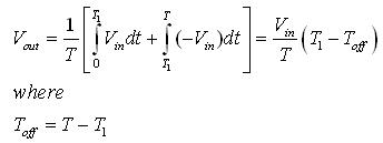 (2)
(2)
From equation 2 it can be seen that for ![]() ,
, ![]() is positive and the current flows from the DC source to load. Both the average load voltage
is positive and the current flows from the DC source to load. Both the average load voltage ![]() and load current Io being positive, the operation of the converter is in first quadrant (Figure 1d). When
and load current Io being positive, the operation of the converter is in first quadrant (Figure 1d). When ![]() ,
, ![]() is negative but Io is positive and the converter operates in fourth quadrant (Figure 1e).
is negative but Io is positive and the converter operates in fourth quadrant (Figure 1e).
|
|
Figure 1a: First and Fourth quadrant converter |
Figure 1b: When switches are on (First quadrant operation) |
|
|
Figure 1c: When freewheeling diodes operate (Fourth quadrant operation) |
|