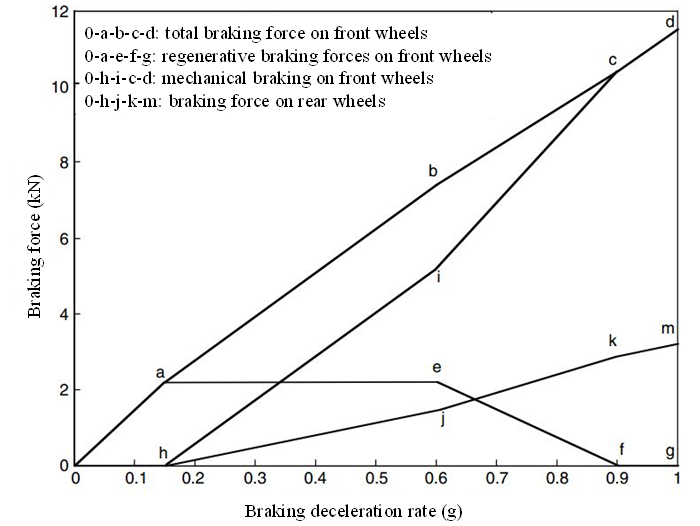
....................................................Figure 4: Braking forces varying with deceleration rate[1]
demand. The pressure signal is regulated and sent to the electric motor controller to control the electric motor to produce the demanded braking torque. Compared with the series braking of both optimal feel and energy recovery, the parallel braking system has a much simpler construction and control system. However, the driver's feeling, and amount of energy recovered are compromised.
Antilock Brake System (ABS)
Active control of the braking force (torque) of the electric motor is easier than the control of the mechanical braking force. Thus, antilock in braking with an electric brake in EVs and HEVs is another inherent advantage, especially for a vehicle with an electric motor on four wheels. Figure 5 conceptually illustrates a scheme of regenerative braking, which can potentially function as an ABS.
The main components of this braking system are the brake pedal, master cylinder, electrically powered and electronically controlled brake actuators, electronically controlled three-port switches (common mode: port 1 open, port 2 close, and port 3 open), fluid accumulator, pressure sensor, and an overall controller unit. The pressure sensor measures the fluid pressure, which represents the driver's desirable braking strength. The fluid is discharged into the fluid accumulator through the electronically controlled three-port switches. This emulates the braking feeling of a conventional braking system. After receiving a braking pressure signal, the overall controller unit determines the braking torques of the front and rear wheels, regenerative braking torque, and mechanical braking torque, according to the traction motor characteristics and control rule. The motor controller (not shown in Figure 5 ) commands the motor to produce correct braking torque, and the mechanical braking controller commands the electrically powered braking actuator to produce correct braking torques for each wheel. The braking actuators are also controlled to function as an antilock system to prevent the wheels from being locked completely. If an electrically powered braking actuator is detected to be a failure, the corresponding three-port switch closes port 3 and opens port 2, and then fluid is directly discharged to the wheel cylinder to produce braking torque. The control strategy is crucial for energy recovery and braking performance.
Figure 6 shows the simulation results of a passenger car, which is experiencing a sudden strong braking on a road with varying road adhesive coefficients. When the commanded braking force is less than the maximum braking force that the ground surface can support without the wheel being locked, the actual braking force follows the commanded braking force. However, when the commanded braking force is greater than the maximum braking force that the ground can support, the actual braking force follows the maximum ground braking force (in a period of 0.5 to 1.5 sec in Figure 6 ). Then, the wheel slip ratios can be controlled in a proper range (usually <25%). The vehicle will have directional stability and short braking distance.