Putting the expressions of M(z) and 1- M(z) in the controller equation
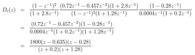
Thus
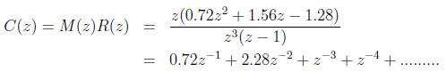
The output response is plotted in Figure 2.
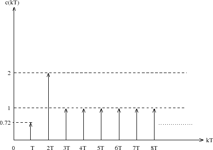 |
Figure 2: Deadbeat Response of The System in Example 2
Note that although c(kT) tracks the unit step perfectly after 3 sampling periods, the maximum overshoot is 128 percent.
This is because of the fact that the digital plant is a type 2 system, hence a deadbeat response without overshoot cannot be obtained for a unit step input.
Thus one can conclude that it is not always possible to design dead beat response without any over shoot.