| |
 |
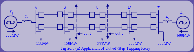
If during out of step condition, the electrical center also appears in the line segment BC, then the required separation is achieved naturally. However, as we know the location of electrical center is not fixed and it depends upon system conditions like ES, ER, number of lines in service, Thevenin's impedances ZS1 and ZS2 etc.
Now, if due to system conditions, the electrical center location shifts to section CD, then uncontrolled system separation will take place at cut - 2, where generation load balance is not obtained.
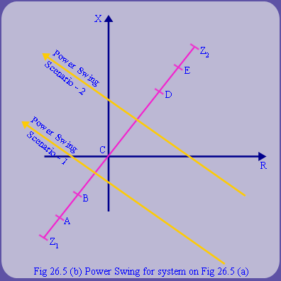
Hence, it is desirable to block distance relay operation on power swings and install an out of step tripping relay at Bus-C. The respective power swings are shown in fig 26.5b. Now, for this scenario, the loss of synchronism requires a transfer trip signal to be generated to breakers at bus B. In general, the point of best separation is not fixed and it depends upon loading and generating conditions. |
| |
Thus, supervising control with system operator intervention may be required to decide the islanding location. Now WAM (Wide Area Measurement) technology has opened up new options for system protection. |

 . In general, this setting should be such that the swing locus will remain between
  for at least a preset interval usually 0.005sec. This time is the operating time of the auxiliary relays which evaluates the sequence of events and determines a loss of synchronism condition. Usually, this represents what is achieved in actual system and hence does not pose any series rejection. Also, the characteristics L1and L2 should not be set so far apart to pick up on load conditions.
  and as maximum loading condition will always have angle below