| |
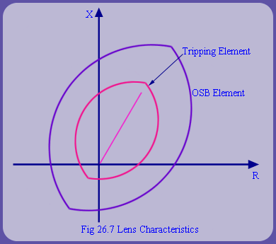 |
When additional blinders as shown in fig 26.6 are used, the 4 cycle travel time from OSB elements has to be monitored with respect to the blinder elements. To restrict the reach of relays, instead of blinders and mho relays, lens type characteristics as shown in fig 26.7 are also used. Many of these functions like tripping, blocking and fault detection can be easily integrated into a single numerical relay with a lot more flexibility to shape characteristics of numerical relays and upcoming WAM technology which use synchronized PMU provide many new options in out of step relaying. However, these developments are beyond the scope of this course. |
| |
Out of Step Protection for Generators |
| |
With large  of generators, it is also likely that electrical center may lie within the generator. When such a situation is detected it is advisable to avoid the knee jerk reaction of tripping the generator. A more beneficial strategy would be to use transfer trip signal to achieve generator function with load generator balancing. of generators, it is also likely that electrical center may lie within the generator. When such a situation is detected it is advisable to avoid the knee jerk reaction of tripping the generator. A more beneficial strategy would be to use transfer trip signal to achieve generator function with load generator balancing. |
| |
Monitoring the Circuit Breaker Tripping |
| |
To avoid stress on the circuit breaker, it is advisable to delay CB trip until after the  point of separation is crossed over and the voltages are coming in phase. Tripping circuit breaker close to out of step condition with separating phasors induces very large transient voltages on circuit breaker which is not very advisable. point of separation is crossed over and the voltages are coming in phase. Tripping circuit breaker close to out of step condition with separating phasors induces very large transient voltages on circuit breaker which is not very advisable. |


