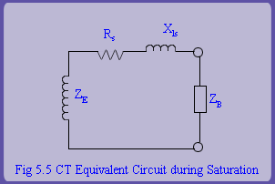
A measurement grade CT has much lower VA capacity than a protection grade CT. A measurement CT has to be accurate over its complete range e.g. from 5% to 125% of normal current. In other words, its magnetizing impedance at low current levels. (and hence low flux levels) should be very high. Note that due to non-linear nature of B-H curve, magnetizing impedance is not constant but varies over the CT's operating range. It is not expected to give linear response (secondary current a scaled replica of the primary current) during large fault currents.
In contrast, for a protection grade CT, linear response is expected up to 20 times the rated current. Its performance has to be accurate in the range of normal currents and upto fault currents. Specifically, for protection grade CT's magnetizing impedance should be maintained to a large value in the range of the currents of the order of fault currents.
When a CT is used for both the purposes, it has to be of required accuracy class to satisfy both accuracy conditions of measurement CTs and protection CTs. In other words, it has to be accurate for both very small and very large values of current. Typically, CT secondary rated current is standardized to 1A or 5A (more common).
However, it would be unreasonable to assume that the linear response will be independent of the net burden on the CT secondary. For simplicity, we refer to the net impedance on the secondary side (neglecting magnetizing impedance) as the CT burden. It is quite obvious that the driving force  required to drive the primary current replica will increase as this burden increases. If this voltage exceeds the designer's set limits, then the CT core will saturate and hence linear response will be lost. Hence, when we say that a CT will give linear response up to 20 times the rated current, there is also an implicit constraint that the CT burden will be kept to a low value. In general, name-plate rating specifies a voltage limit on the secondary (e.g., 100 V) up to which linear response is expected. If the CT burden causes this voltage to be exceeded, CT saturation results.
|