Module 2 : Current and Voltage Transformers
Lecture 5 : Introduction to CT
5.2 Equivalent Circuit of CT

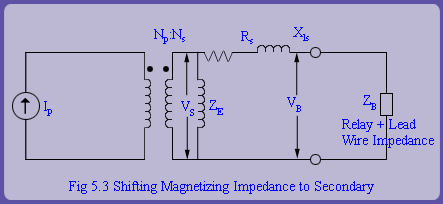
  After application of the above steps, the CT equivalent circuit is as shown in the fig 5.3. Note that the secondary winding resistance and leakage reactance is not neglected as it will affect the performance of CT. The total impedance on the secondary side is the sum of relay burden, lead wire resistance and leakage impedance of secondary winding. Therefore, the voltage developed in the secondary winding depends upon these parameters directly.

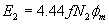
  The secondary voltage developed by the CT has to be monitored because as per the transformer emf equation, the flux level in the core depends upon it. The transformer emf equation is given by,
 
 
where is the peak sinusoidal flux developed in the core. If corresponding to this flux is above the knee point, it is more or less obvious that the CT will saturate. During saturation, CT secondary winding cannot replicate the primary current accurately and hence, the performance of the CT deteriorates.

Thus, we conclude that in practice, while selecting a CT we should ascertain that it should not saturate on the sinusoidal currents that it would be subjected to.

 
Use of numerical relays due to their very small burden vis-a-vis solid state and electromechanical relays, improves the CT performance. CT is to be operated always in closed condition. If the CT is open circuited, all the current Ip/N, would flow through Xm. This will lead to the development of dangerously high level of voltage in secondary winding which can even burn out the CT.

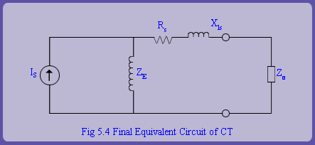
We can further, simplify the equivalent circuit of a CT by transferring the current source (through the ideal transformer) to the secondary side. Thus, the equivalent circuit of the CT is as shown in fig 5.4.
 
4