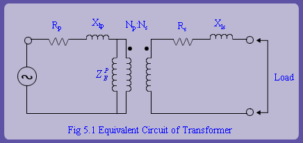
To begin with, equivalent circuit of a CT is not much different from that of a regular transformer (fig 5.1). However, a fundamental difference is that while regular power transformers are excited by a voltage source, a current transformer has current source excitation. Primary winding of the CT is connected in series with the transmission line. The load on the secondary side is the relaying burden and the lead wire resistance.
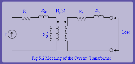
Total load in ohms that is introduced by CT in series with the transmission line is insignificant and hence, the connection of the CT does not alter current in the feeder or the power apparatus at all. Hence from modeling perspectives it is reasonable to assume that CT primary is connected to a current source. Therefore, the CT equivalent circuit will look as shown in fig 5.2. The remaining steps in modeling are as follows:
As impedance in series with the current source can be neglected, we can neglect the primary winding resistance and
leakage reactance in CT modeling.
For the convenience in analysis, we can shift the magnetizing impedance from the primary side to the secondary side of