Module 10 :
Differential Protection of Bus, Transformer and Generator
Lecture 39 :
Transformer Protection
Example (contd..)
Remark 3: When dealing with three phase transformers, the transformer connections like Y-Y or also play a role in determining CT secondary interconnections to establish circulating current scheme. This is because of the phase shifts typically of the order of that result in the line currents when we move from primary to secondary side of the power transformer. Fig 39.3 shows the typical connections for star-delta transformer bank for establishing the circulatory currents. The study of the circuit brings out the following important rule for interconnection of CT secondary for transformers: “If the power transformer winding are connected in Y configuration, use configuration for corresponding CT secondary interconnections" (and vice-versa).
Remark 4: With numerical relays such interconnection complexity can be easily handled in software. After, specifying the turns ratio and the phase shift from primary to secondary, it should be possible to work out the expected secondary differential current by simple calculation.
Role of Percentage Differential Protection
So far, our discussion has focused on an ideal transformer. However, practical transformers and CTs pose additional challenge to protection.
(1)
The primary of transformer will carry no load current even when the secondary is open circuited. This will lead to
differential current on which the protection scheme should not operate.
(2)
It is not possible to exactly match the CT ratio as per equation (1). This would also lead to differential currents under
healthy conditions.
(3)
If the transformer is used with an off nominal tap, then differential currents will arise as equation (2) is not satisfied
even under healthy conditions. However, tap position can be read in numerical protection scheme and accounted by equation (2). This would make the numerical protection scheme adaptive.
To prevent the differential protection scheme from picking up under such conditions, a percentage differential protection scheme is used. (see fig 39.4 )
It improves security at the cost of sensitivity. Notice an offset of to account for the no load current. The current on the x-axis is the average current of primary and secondary winding referred to primary. It indicates the restraining current while the corresponding difference on Y-axis represents the differential current. For reference current direction see fig 39.1.
The differential protection will pick up if magnitude of differential current is more than a fixed percentage of the restraining current.

 also play a role in determining CT secondary interconnections to establish circulating current scheme. This is because of the phase shifts typically of the order of
  that result in the line currents when we move from primary to secondary side of the power transformer. Fig 39.3 shows the typical connections for star-delta transformer bank for establishing the circulatory currents. The study of the circuit brings out the following important rule for interconnection of CT secondary for
  transformers: “If the power transformer winding are connected in Y configuration, use
  configuration for corresponding CT secondary interconnections" (and vice-versa).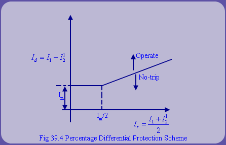
 to account for the no load current. The current on the x-axis is the average current of primary and secondary winding referred to primary. It indicates the restraining current while the corresponding difference on Y-axis represents the differential current. For reference current direction see fig 39.1.

