| |
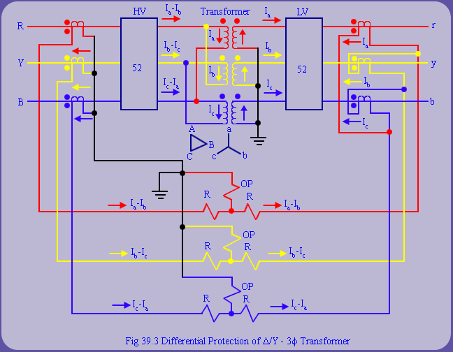
Remarks 1: Sometimes due to ‘odd turns ratio' involved in primary, it may not be possible to obtain matching CTs on the secondary. In such situations ‘auxiliary CTs' are used either on primary or secondary (or both sides) to obtain circulatory currents in absence of internal faults. Primary of the auxilliary CT is connected in series with secondary of main CT. Secondary of auxilliary CT participates in the circulating current scheme. |
| |
Remark 2: The circulating current scheme described above has been traditionally used with electromechanical and solid state relays. However in case of numerical relays, such physical connections are no more required. Given turns ratio  and CTs ratio and CTs ratio  and and  , one can work out the expected current in secondary of transformer (in absence of internal fault). Hence, auxiliary CTs become redundant and the transformer connections are simplified drastically. Thus, with numerical relaying most of the hardware connections and circulatory currents can be easily accounted in software. Further, with digital protection systems differential protection can be implemented by either 'sample by sampe' comparison or by first computing the phasors and then comparing them. , one can work out the expected current in secondary of transformer (in absence of internal fault). Hence, auxiliary CTs become redundant and the transformer connections are simplified drastically. Thus, with numerical relaying most of the hardware connections and circulatory currents can be easily accounted in software. Further, with digital protection systems differential protection can be implemented by either 'sample by sampe' comparison or by first computing the phasors and then comparing them.
Phasor computation approach will involve a delay equal to the time required for moving window to latch on to post fault phasor. Conversely, 'sample by sample' comparison approach can be faster but it is more prone to picking up to noise or trannsients. Hence, even it has to be slowed down by 'polling scheme'. In this scheme, we increment a winter, whenever large enough differential is detected. If counter is positive and differential is below threshold, we decrement the counter. If the counter 'ensures as threshold, a trip decision is issued. |