| |
Complications of Magnetizing Inrush (contd..) |
| |
Our analysis so has a discrepancy. As per our analysis, flux and current wave shape in fig 39.6 should persist till infinity i.e. it should represent the steady state flux and current waveform in the core. However, we also know that steady state flux and current waveform is as per fig 39.7. The resulting discrepancy is a consequence of our simplifying assumption viz, core is ideal and the winding is non resistive. If we also model the winding resistance, we would observe that the voltage available at the ideal transformer primary terminals would reduce drastically due to large voltage drop in the winding impedance during inrush condition. Consequently, the effect should propagate and reduce flux in the core. If the flux in the core reduces, so would magnetizing current. Thus, each cycle would have smaller magnetization current peak and the magnetizing current and flux would finally approach the one produced by steady state phasor equation. |
| |
To summarize the discussion so far, |
| 1. |
Transformer when energized can be subjected to large inrush currents. |
| 2. |
Inrush current can trip differential protection of transformers. |
| |
Some methodology to detect inrush has to be devised and transformer differential protection has to be inhibited from tripping during this condition. |
| |
Detection of Inrush Current and Overexcitation Condition |
| |
Appreciable differential current can result due to either inrush or overexcitation of transformer. When a transformer is overexcited, then from the relationship 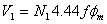 , we can infer that peak sinusoidal flux is large. This implies that transformer core will be driven into saturation for an interval in each half cycle. Due to this, there would be distortion from the sinusoidal magnetization current. During saturation, the corresponding magnetizing current can be quite large and on the resulting differential the protection system may issue a trip decision by confusing overexcitation for an internal fault. Hence, in practice restraint has to be provided for both overexcitation and inrush current condition. There are three possible ways in which this can be achieved. , we can infer that peak sinusoidal flux is large. This implies that transformer core will be driven into saturation for an interval in each half cycle. Due to this, there would be distortion from the sinusoidal magnetization current. During saturation, the corresponding magnetizing current can be quite large and on the resulting differential the protection system may issue a trip decision by confusing overexcitation for an internal fault. Hence, in practice restraint has to be provided for both overexcitation and inrush current condition. There are three possible ways in which this can be achieved. |
| |
Analysis of the current waveform indicates that inrush current is rich in second harmonic and current during overfluxing has a large fifth harmonic component. Thus, if we compute the second and fifth harmonic current in  , then, we can provide following logic for restraining operation of differential protection. Restrain operation of differential protection if , then, we can provide following logic for restraining operation of differential protection. Restrain operation of differential protection if |
| 1. |
 for restrain (No load magnetization current) for restrain (No load magnetization current) |
| |
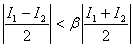
(Where  is the slope of the % differential characteristics) is the slope of the % differential characteristics) |