| |
Detection of Inrush Current and Overexcitation Condition (contd..) |
| (3) |
Flux Restraint Scheme (contd..) |
| |
This can be easily worked out as follows.
Let the voltage at the terminal of the transformer be v(t), current i(t) and let L be the leakage inductance of the winding. If we neglect the resistance of the winding, then, |
| |
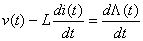
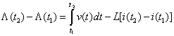
Using trapezoidal rule of integration, we get |
| |
From the above equation (9) we can deduce the following generic relationship. |
| |
Operation on the unsaturated region of magnetizing curve produces large value of slope  . Since, the fault or overexcitation (saturated) regions have smaller . Since, the fault or overexcitation (saturated) regions have smaller
 slopes, we can now distinguish internal fault from the saturation condition by following counter scheme. slopes, we can now distinguish internal fault from the saturation condition by following counter scheme.
If current differential indicates trip and  , increment counter. , increment counter. |
| |

else if  and and  , then , then

else if  and and  , then , then

|
| |
If there is an internal fault in the system, then  will monotonically increase and once crosses a known threshold, trip decision will be issued. On the other hand, during inrush or over excitation the will monotonically increase and once crosses a known threshold, trip decision will be issued. On the other hand, during inrush or over excitation the  will alternate between low slope and high slope region depending upon whether the core is in saturation or not. Thus, the counter will indicate a small tooth kind of behavior with will alternate between low slope and high slope region depending upon whether the core is in saturation or not. Thus, the counter will indicate a small tooth kind of behavior with  being below the threshold value. Hence, operation of the different protection scheme would be restrained in this region. being below the threshold value. Hence, operation of the different protection scheme would be restrained in this region. |
| |
Remark 5: We have illustrated the basic principle so far using a single phase transformer for simplicity. However, in practice, we use both three phase two winding and three phase three winding (primary, secondary and tertiary) transformers. The basic principle of differential protection is the same but we now have to scale up to multiple phases. For a three phase (two winding) transformer, there would be 3 trip currents (one per phase) and three restraining currents (one per phase). For three phase three winding transformers, two restraining per phase are required. |





