|
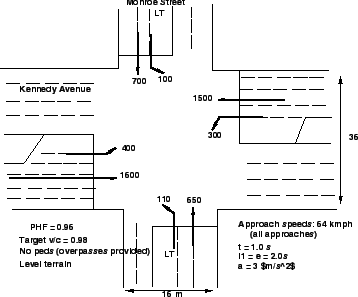
An isolated suburban intersection of two major arterial is to be signalized
using a full actuated controller.
Area detection is to be used, and there are no driveways or other potential
entry points for vehicles within 90 m of the STOP line on all approaches.
The intersection is shown in the figure and all volumes have already been
converted to tvus for convenience.
Left-turn slots of 75 m in length are provided for each approach.
The tvu conversions assume that a protected left-turn phase will be provided
for all approaches.
Figure 1:
Intersection for the Example
 |
Step 1: Phasing:
The problem statement indicates that protected left-turn phasing will be
implemented on all approaches.
Note that Kennedy Avenue has double left-turn lanes in each direction and that
Monroe Street has a single left-turn lane in each direction.
At a heavily utilized intersection such as this, quad-eight phasing would be
desirable.
Each street would have an exclusive LT phase followed by a leading green in the
direction of heavier LT flow and a TH/RT phase.
Such phasing provides much flexibility in that LT phasing is always optional
and can be skipped in any cycle in which no LT demand is noted.
The resulting signalization has a maximum of four phases in any given cycle and
a minimum of two.
It is treated as a four-phase signal, as this option leads to the maximum lost
times.
Quad-eight phasing involves overlaps that would be taken into account if this
were a pre-timed signal.
As an actuated signal, the worst-case cycle, however, would occur when there
are no overlap periods.
This would occur when the LT flow in opposing directions are equal.
Thus, the signal timing will be considered as if this were a simple four-phase
operation without overlaps.
The controller, however, will allow one protected LT to be terminated before
the opposing protected LT, creating a leading green phase.
The four phases are:
- Phase I-Protected LT for Kennedy Avenue
- Phase 2-TH/RT for Kennedy Avenue
- Phase 3-Protected LT for Monroe Street
- Phase 4-TH/RT for Monroe Street
Step 2: Unit Extension:
For approach speeds of 64 kmph, the recommended unit extension (from Table) is
3.5 s.
Step 3: Minimum Green Times and Detector Placement:
The problem specifies that area detection shall be employed.
For area detection, the far end of the detection zone is placed such that the
passage time is equal to unit extension.
Since all approaches (including LT approaches) have a 64 kmph approach speed,
the far end of detectors should be located as follows:
The near end of the detection zone would be placed within 0.3 m of the STOP
line.
The minimum green time for area detection is variable, based on the number of
vehicles sensed within the detection area when the green is initiated.
The value can vary from the time needed to service one waiting vehicle to the
time needed to service Int(62/6) = 11 vehicles.
The range of minimum green times can be established for each approach.
In this case, all values will be equal, as the approach speeds are the same for
all approaches and the detector location is common to every approach, including
the LT lanes, all of which are long enough to accommodate a 62 m setback.
Step 4: Critical-Lane Volumes:
As the volumes given have already been converted to tvus, critical-lane volumes
for each phase are easily identified:
- Phase 1 (Kennedy Ave, LT) - 400/2 = 200 tvu/h
- Phase 2 (Kennedy Ave, TH/RT) - 1,600/4 = 400 tvu/h
- Phase 3 (Monroe St, LT) - 110/1 = 110 tvu/h
- Phase 4 (Monroe St, TH/RT) - 700/2 = 350 tvu/h
Therefore, VC = (200+400+110+700) = 1,060 tvu/h.
Step 5: Yellow & All-Red times
With a 64 kmph average approach speed for all movements, the  may be
estimated as (64 + 8) = 72 kmph, and the may be
estimated as (64 + 8) = 72 kmph, and the  may be estimated as (64 - 8)
= 56 kmph.
Then: may be estimated as (64 - 8)
= 56 kmph.
Then:
There are four phases in the worst-case cycle.
The total lost time is equal to the sum of the yellow and all-red intervals in
the cycle:
L = 2*5.8 + 2*7.0 = 25.6 sec.
Step 6: Maximum Green Times and the Critical Cycle:
The initial cycle length for determining maximum green time is:
 = 25.6/[1-1060/(1615*0.96*0.98)] = 84.8 sec.
Green times are found as: = 25.6/[1-1060/(1615*0.96*0.98)] = 84.8 sec.
Green times are found as:
With area detection, the minimum green for all lane groups, including LT lanes,
can be as high as 24.0 s.
This is inconsistent with  values for the LT Phases 1 and 3.
Increasing the maximum greens beyond the computed values, however, will lead to
an excessively long critical cycle length.
Thus, it is recommended that the LT lanes use point detectors, placed so that
the values for the LT Phases 1 and 3.
Increasing the maximum greens beyond the computed values, however, will lead to
an excessively long critical cycle length.
Thus, it is recommended that the LT lanes use point detectors, placed so that
the  for Phases 1 and 3 is a constant 4.0 s.
The above results will work in this scenario.
The results for Phases 2 and 4 (through phases) are close to the high
value of for these phases, but would provide some flexibility even in
peak periods.
It is, therefore, not recommended that any of these times be arbitrarily
increased.
The critical cycle length becomes: for Phases 1 and 3 is a constant 4.0 s.
The above results will work in this scenario.
The results for Phases 2 and 4 (through phases) are close to the high
value of for these phases, but would provide some flexibility even in
peak periods.
It is, therefore, not recommended that any of these times be arbitrarily
increased.
The critical cycle length becomes:
 = 16.8 + 5.8 + 33.5 + 5.8 + 9.2 + 7.0 + 29.3 + 7.0 = 114.4 sec = 16.8 + 5.8 + 33.5 + 5.8 + 9.2 + 7.0 + 29.3 + 7.0 = 114.4 sec
|
|