| |
| | |
|
Figure 1:
Operation of an Actuated Phase
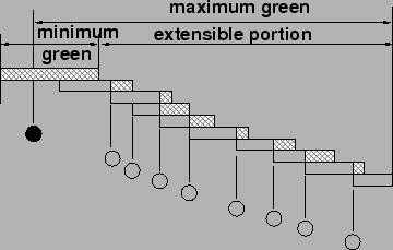 |
The Fig. 1 illustrates the operation of an actuated phase
based on the three critical settings: minimum green, maximum green, and unit or
vehicle extension.
When the green is initiated for a phase, it will be at least as long as the
minimum green period.
The controller divides the minimum green into an initial portion and a portion
equal to one unit extension.
If an additional call is received during the initial portion of the
minimum green, no time is added to the phase, as there is sufficient time
within the minimum green to cross the STOP line (yellow and all-red intervals
take care of clearing the intersection).
If a call is received during the last U seconds (Unit Extension) of the
minimum green, U seconds of green are added to the phase.
Thereafter, every time an additional call is received during a unit
extension of U seconds, an additional period of U seconds is added to the
green.
Note that the additional periods of U seconds are added from the time of the
actuation or call.
They are not added to the end of the previous unit extension, as this would
accumulate unused green times within each unit extension and include them in
the total green period.
The green is terminated in one of two ways:
- a unit extension of U seconds expires without an additional actuation,
- the maximum green is reached.
The maximum green begins timing out when a call on a competing phase is
noted.
During the most congested periods of flow, however, it may be assumed that
demand exists more or less continuously on all phases.
The maximum green, therefore, begins timing out at the beginning of the green
period in such a situation.
Now-a-days, in India, detectors are placed mostly at stop lines.
In that case, the green times for phases are primarily determined by arrival
headway.
The green time is extended until the gap between two vehicles becomes equal to
or greater than the pre-determined threshold value.
Generally threshold of 4 seconds is considered.
Table 1:
Recommended Detector Locations & Timing Parameters
| Approach |
Detector Set-Back |
Mimi-mum |
Passage |
| Speed |
(To front of loop) |
Green |
Time |
| (kmph) |
(m) |
(sec) |
(sec) |
| 24 |
12 |
8.0 |
3.0 |
| 32 |
18 |
10.0 |
3.0 |
| 40 |
24 |
12.0 |
3.0 |
| 48 |
30 |
14.0 |
3.5 |
| 56 |
41 |
18.0 |
3.5 |
| 64 |
52 |
22.0 |
3.5 |
| 72+ |
Volume density or multiple detectors recommended |
- Detectors on minor approaches only.
- Major phase receives a minimum green interval.
- The green remains on the main street until a call for service on
the side street is registered.
- If the main street has had enough green, the side street is given the
green for just enough time to guarantee that its vehicles are processed.
- Usually Point Detectors are used.
- Detectors can be placed at either stop line or upstream location.
- It can be used effectively in a coordinated signal system.
- Relative to pre-timed control, it reduces the delay incurred by the
major-road through movements during periods of light traffic.
- It does not require detectors for the major-road through movement phases
and hence, its operation is not compromised by the failure of these detectors.
- Generally the main street indeed has the green whenever possible.
Figure 2:
Semi-Actuated Control
 |
- Continuous demand on the phases associated with one or more minor
movements can cause excessive delay to the major road through movements if the
maximum green and passage time parameters are not appropriately set.
- Detectors must be used on the minor approaches, thus requiring
installation and ongoing maintenance.
- It also requires more training than that needed for pre-timed control.
|
|
| | |
|
|
|