| |
| | |
|
Figure 1:
Case study:progression on a one way street
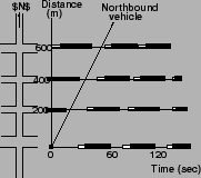 |
In Fig. 1 a one-way arterial is shown with the link lengths
indicated.
Assuming no vehicles are queued at the signals, the ideal offsets can be
determined if the platoon speed is known.
For the purpose of illustration, a platoon speed of 60 fps is assumed.
The offsets are determined according to Eqn. ![[*]](file:/usr/local/share/lib/latex2html/icons/crossref.png) .
Next the time-space diagram is constructed according to the following rules: .
Next the time-space diagram is constructed according to the following rules:
- The vertical should be scaled so as to accommodate the dimensions of the
arterial, and the horizontal so as to accommodate at least three to four cycle
lengths.
- The beginning intersection should be scaled first, usually with main
street green initiation at t=0, followed by periods of green and red.
- The main street green of the next downstream signal should be located
next, relative to t=0 and at the proper distance from t he first intersection.
With this point located, the periods of green, yellow and red for this signal
are filled in.
- This procedure is repeated for all other intersections working one at a
time.
Figure 2:
Time space diagram for case study
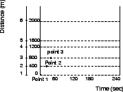 |
Figure 3:
Vehicle trajectory and green wave in a progressed movement
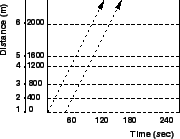 |
Fig. 2 shows the time-space diagram for the illustration
mentioned previously.
Fig. 3 explores some features of the time-space diagram.
It sometimes happens that there are vehicles stored in block waiting for a
green light.
These may be stragglers from the last platoon, vehicles that turned into the
block, or vehicles that came out of parking lots or spots.
The ideal offset must be adjusted to allow for these vehicles, so as to avoid
unnecessary stops.
The ideal offset can then be given as:
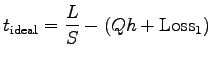 |
(1) |
where,  = number of vehicles queued per lane, veh, = number of vehicles queued per lane, veh,  = discharge headway of
queued vehicle, sec/veh, and = discharge headway of
queued vehicle, sec/veh, and  = loss time associated with vehicles
starting from rest at the first downstream signal.
If it is known that there exists a queue and its size is known approximately,
then the link offset can be set better than by pretending that no queue exists.
There can be great cycle-to-cycle variation in the actual queue size, although
its average size may be estimated.
Even then, queue estimation is a difficult and expensive task and should be
viewed with caution. = loss time associated with vehicles
starting from rest at the first downstream signal.
If it is known that there exists a queue and its size is known approximately,
then the link offset can be set better than by pretending that no queue exists.
There can be great cycle-to-cycle variation in the actual queue size, although
its average size may be estimated.
Even then, queue estimation is a difficult and expensive task and should be
viewed with caution.
|
|
| | |
|
|
|