| |
| | |
|
For signals that are closely spaced, it is necessary to coordinate the green
time so that vehicles may move efficiently through the set of signals.
In some cases, two signals are so closely spaced that they should be considered
to be one signal.
In other cases, the signals are so far apart that they may be considered
independently.
Vehicles released from a signal often maintain their grouping for well over
335m.
There are four major areas of consideration for signal coordination:
- Benefits
- Purpose of signal system
- Factors lessening benefits
- Exceptions to the coordinated scheme
Figure 1:
Vehicle trajectory
 |
The most complex signal plans require that all signals have the same cycle
length.
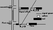
Fig. 1 illustrates path (trajectory) that a vehicle takes as time
passes.
At  , the first signal turns green.
After some lag, the vehicle starts and moves down the street.
It reaches the second signal at some time , the first signal turns green.
After some lag, the vehicle starts and moves down the street.
It reaches the second signal at some time  .
Depending on the indication of that signal, it either continues or stops.
The difference between the two green initiation times is referred to as the
signal offset, or simply as the offset.
In general, the offset is defined as the difference between green initiation
times, measured in terms of the downstream green initiation relative to the
upstream green initiation.
It is common to consider the benefit of a coordination plan in terms of a
cost or penalty function; a weighted combination of stops
and delay, and other terms as given here: .
Depending on the indication of that signal, it either continues or stops.
The difference between the two green initiation times is referred to as the
signal offset, or simply as the offset.
In general, the offset is defined as the difference between green initiation
times, measured in terms of the downstream green initiation relative to the
upstream green initiation.
It is common to consider the benefit of a coordination plan in terms of a
cost or penalty function; a weighted combination of stops
and delay, and other terms as given here:
 |
(1) |
The object is to make this dis-benefit as small as possible.
The weights  and and  are coefficients to be specified by the engineer or
analyst.
The values of and may be selected so as to reflect the estimated
economic cost of each stop and delay.
The amounts by which various timing plans reduce the cost, can then be used in
a cost-benefit analysis to evaluate alternative plans.
The conservation of energy and the preservation of the environment have grown
in importance over the years.
Given that the vehicles must travel, fuel conservation and minimum air
pollution are achieved by keeping vehicles moving as smoothly as possible at
efficient speeds.
This can be achieved by a good signal-coordination timing plan.
Other benefits of signal coordination include, maintenance of a preferred
speed, possibility of sending vehicles through successive intersections in
moving platoons and avoiding stoppage of large number of vehicles.
The physical layout of the street system and the major traffic flows determine
the purpose of the signal system.
It is necessary to consider the type of system, whether one-way arterial,
two-way arterial, one-way,two-way, or mixed network.
the capacities in both directions on some streets, the movements to be
progressed, determination of preferential paths
Among the factors limiting benefits of signal coordination are the following: are coefficients to be specified by the engineer or
analyst.
The values of and may be selected so as to reflect the estimated
economic cost of each stop and delay.
The amounts by which various timing plans reduce the cost, can then be used in
a cost-benefit analysis to evaluate alternative plans.
The conservation of energy and the preservation of the environment have grown
in importance over the years.
Given that the vehicles must travel, fuel conservation and minimum air
pollution are achieved by keeping vehicles moving as smoothly as possible at
efficient speeds.
This can be achieved by a good signal-coordination timing plan.
Other benefits of signal coordination include, maintenance of a preferred
speed, possibility of sending vehicles through successive intersections in
moving platoons and avoiding stoppage of large number of vehicles.
The physical layout of the street system and the major traffic flows determine
the purpose of the signal system.
It is necessary to consider the type of system, whether one-way arterial,
two-way arterial, one-way,two-way, or mixed network.
the capacities in both directions on some streets, the movements to be
progressed, determination of preferential paths
Among the factors limiting benefits of signal coordination are the following:
- inadequate roadway capacity
- existence of substantial side frictions, including parking, loading,
double parking, and multiple driveways
- wide variability in traffic speeds
- very short signal spacing
- heavy turn volumes, either into or out of the street
All signals cannot be easily coordinated.
When an intersection creating problems lies directly in the way of the plan
that has to be designed for signal coordination, then two separate systems, one
on each side of this troublesome intersection, can be considered.
A critical intersection is one that cannot handle the volumes delivered to it
at any cycle length.
The time-space diagram is simply the plot of signal indications as a function
of time for two or more signals.
The diagram is scaled with respect to distance, so that one may easily plot
vehicle positions as a position of time.
Fig. 2 is a time-space diagram for two intersections.
Figure 2:
Time space diagram
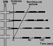 |
The standard conventions are used in Fig. 2: a green
signal indication is shown by a blank or thin line, amber by a shaded line and
red by a solid line.
For purpose of illustration of trajectory in the time space diagram for
intersections, a northbound vehicle going at a constant speed of 40fps is
shown.
The ideal offset is defined as the offset that will cause the
specified objective to be best satisfied.
For the objective of minimum delay, it is the offset that will cause minimum
delay.
In Fig. 2, the ideal offset is 25 sec for that case and
that objective.
If it is assumed that the platoon was moving as it went through the upstream
intersection then the ideal offset is given by
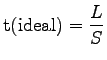 |
(2) |
where:  = ideal offset,sec, = ideal offset,sec,  = block length, m, = block length, m,  = vehicle
speed, mps. = vehicle
speed, mps.
|
|
| | |
|
|
|