|
The signal design procedure involves six major steps.
They include: (1) phase design, (2) determination of amber time and
clearance time, (3) determination of cycle length, (4) apportioning of green
time, (5) pedestrian crossing requirements, and (6) performance evaluation
of the design obtained in the previous steps.
The objective of phase design is to separate the conflicting movements in an
intersection into various phases, so that movements in a phase should have no
conflicts.
If all the movements are to be separated with no conflicts, then a large number
of phases are required.
In such a situation, the objective is to design phases with minimum conflicts
or with less severe conflicts.
There is no precise methodology for the design of phases.
This is often guided by the geometry of the intersection, the flow pattern
especially the turning movements, and the relative magnitudes of flow.
Therefore, a trial and error procedure is often adopted.
However, phase design is very important because it affects the further design
steps.
Further, it is easier to change the cycle time and green time when flow pattern
changes, where as a drastic change in the flow pattern may cause considerable
confusion to the drivers.
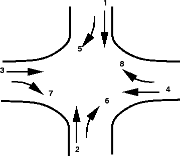
To illustrate various phase plan options, consider a four legged intersection
with through traffic and right turns. Left turn is ignored. See
Figure 1.
Figure 1:
Four legged intersection
 |
The first issue is to decide how many phases are required.
It is possible to have two, three, four or even more number of phases.
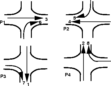
Two phase system is usually adopted if through traffic is significant compared
to the turning movements.
For example in Figure 2, non-conflicting through traffic 3 and 4 are
grouped in a single phase and non-conflicting through traffic 1 and 2 are
grouped in the second phase.
Figure 2:
Movements in two phase signal system
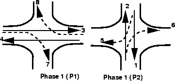 |
However, in the first phase flow 7 and 8 offer some conflicts and are called
permitted right turns.
Needless to say that such phasing is possible only if the turning movements are
relatively low.
On the other hand, if the turning movements are significant, then a four phase
system is usually adopted.
There are at least three possible phasing options.
For example, figure 3 shows the most simple and trivial phase plan.
Figure 3:
Movements in four phase signal system: option 1
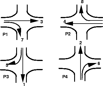 |
where, flow from each approach is put into a single phase avoiding all
conflicts.
This type of phase plan is ideally suited in urban areas where the turning
movements are comparable with through movements and when through traffic and
turning traffic need to share same lane.
This phase plan could be very inefficient when turning movements are relatively
low.
Figure 4 shows a second possible phase plan option where opposing
through traffic are put into same phase.
Figure 4:
Movements in four phase signal system: option 2
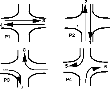 |
The non-conflicting right turn flows 7 and 8 are grouped into a third phase.
Similarly flows 5 and 6 are grouped into fourth phase.
This type of phasing is very efficient when the intersection geometry permits
to have at least one lane for each movement, and the through traffic volume is
significantly high.
Figure 5 shows yet another phase plan.
However, this is rarely used in practice.
Figure 5:
Movements in four phase signal system: option 3
 |
There are five phase signals, six phase signals etc. They are normally
provided if the intersection control is adaptive, that is, the signal phases
and timing adapt to the real time traffic conditions.
|