| |
| | |
|
Provide Channelization for an intersection having EW as the major road.
The major and minor roads intersect at right angles.
The design vehicle is WB-50 (R=25m) and design speed is 45 kmph.
The intersection is unsignalized.
EW road has 2 lanes in each direction and NS has 1 lane for each direction.
Take lane width =3.6 m.
Provide bullet nose median ends.
Also provide channelizing island for free right for WS bound traffic.
:
The approach taper for auxiliary lane is equal to
 .
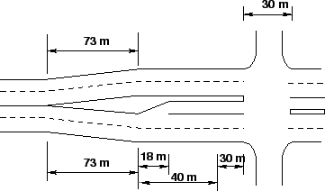
The deceleration Taper is taken as 40 m.
Considering a 1:10 taper, the Bay Taper is found out to be 18 m.
Let the storage length = 30 m (say).
Now from Table. .
The deceleration Taper is taken as 40 m.
Considering a 1:10 taper, the Bay Taper is found out to be 18 m.
Let the storage length = 30 m (say).
Now from Table. ![[*]](file:/usr/local/share/lib/latex2html/icons/crossref.png) , it is found that for bullet nose
median end, Median Opening = 30 m.
The dimensions of all the components of the auxiliary lane are shown in
Fig. 1. , it is found that for bullet nose
median end, Median Opening = 30 m.
The dimensions of all the components of the auxiliary lane are shown in
Fig. 1.
Figure 1:
Dimensions of components of the auxiliary lane for the intersection
 |
The width required for the WB- 50 semi-trailer unit is found to be about 6.5 m.
Additional 0.5 m is provided on the outer side and 0.3 m is provided on the
inner side away from the edge of the island.
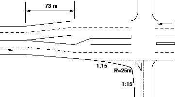
For the turning roadway for the W-S direction, the single offset method is used.
At 0.3 + 0.5 + 6.5 = 7.3 m from the island edge, a circle of radius 25 m is laid
out.
Then two tapers of slope 1:15 is laid out on either side of the arc to join with
the straight edge on either side.
Thus the Channelization is provided for the W-S approach.
Similar method can be used for designing the Channelization schemes of the other
directions as well.
The Channelization for the W-S approach is shown in
Fig. 2.
Figure 2:
Channelization for the W-S direction with traffic island
 |
Following the principles of Channelization suggest suitable island schemes
for the following intersections (considering both high relative speed and low
relative speed) (Figs. 3,
4)
- Y – Intersection (Figs. 5,
6 and 7)
- Skewed intersection (Figs. 8,
9 and 10)
Figure 3:
Wye Intersection
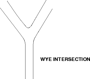 |
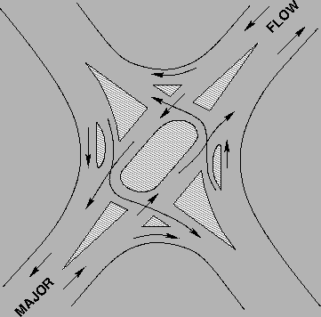
Figure 4:
Skewed Cross Road
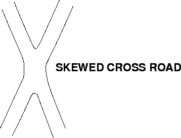 |
Figure 5:
(a) Y - Intersection
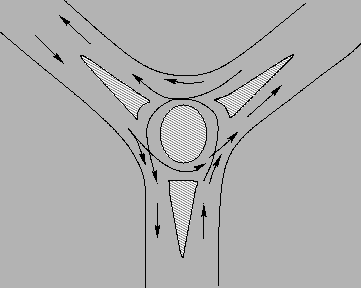 |
Figure 6:
(b) Y - Intersection
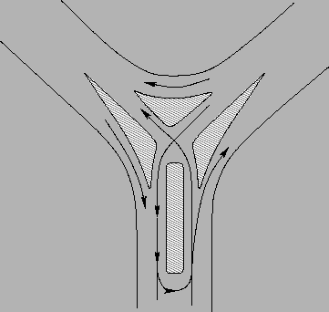 |
Figure 7:
(c) Y - Intersection
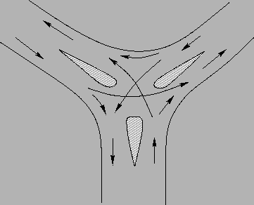 |
Figure 8:
(a) Skewed Intersection
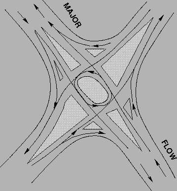 |
Figure 9:
(b) Skewed Intersection
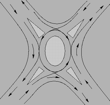 |
Figure 10:
(c) Skewed Intersection
 |
|
|
| | |
|
|
|