| |
| | |
|
The general guidelines to be followed in the design of median islands
(separators of opposing traffic flows) are:
- The approach noses should be offset 0.6 to 1.8 m from through lanes to
minimize accidental impacts.
- Shape should be based on design turning paths and island function.
(Generally parabolic or circular arcs are used)
- The length of median before the intersection is related to approach speed
(normally 3 sec driving time to intersection). It is also affected by available
widths, taper designs and local constraints.
- The width of the medians should serve its primary intended function.
- The median should always be provided well past crest vertical curves.
Fig. 1 shows the general design elements of medians
provided just at the approach to a intersection.
Figure 1:
Design Criteria for raised median approaches to intersections
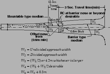 |
The required median widths for performing their intended functions are provided
by AASHTO and are shown in Table. 1 below.
These widths are empirical and can be applied at an intersection with reasonable
efficiency.
Table 1:
Basic median functions and their required width
| Function |
Width in meter |
| |
Minimum |
Desirable |
| Separation of opposing traffic |
1.2 |
3 |
| Provision of pedestrian refuse |
1.8 |
4.2 |
| Provision of storage for left-turn vehicles |
4.8 |
6 |
| Provision for protection of vehicles crossing |
7.5 |
9 |
| through lanes |
|
|
| Provision for U turns, inside to outside lanes |
4.8 |
6 |
| Provision for U-turns, inside to inside lanes |
7.8 |
9 |
Auxiliary lanes are used under conditions of
relatively high traffic volumes in the intersections.
In these cases, traffic congestion problems can be significantly alleviated with
auxiliary lanes to handle turning movements.
The median lane should be 12 feet (3.6m), but not less than 10 feet (3.0m) wide
and should be clearly marked for this purpose.
Auxiliary lanes can also be introduced to provide for both left turns and right
turns at intersections.
The need for such lanes is determined by capacity analysis and the acceptable
level of service designated for the facility.
The lanes should be at least 2.7m wide for reconstruction and resurfacing
projects and at least 3.0m, preferably 3.6m for new construction projects.
Auxiliary lane shoulders can be reduced to 0.6 m wide on rural sections and 0 m
wide on sections with curb and gutter.
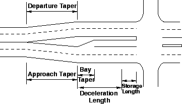
The length of auxiliary lanes consists of five components:
- Approach Taper
- Deceleration Length
- Bay Taper
- Storage Length, and
- Departure Taper.
A typical auxiliary lane with the components are shown in
Fig. 2 below.
Figure 2:
Components of Auxiliary Lane
 |
These are discussed in detail in the following section.
- Approach Taper- The length of the approach taper varies with
operating speeds.
Guidelines for determining lengths are:
(i) For speeds 70 kmph and over:
 , and
(ii) For speeds under 70 kmph: , and
(ii) For speeds under 70 kmph:
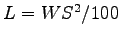 where,
 is the length of entering taper in m, is the length of entering taper in m,
 is the width to be tapered in m, and is the width to be tapered in m, and
 is the operating Speed in kmph. is the operating Speed in kmph.
- Deceleration Length- The deceleration length is that required
for a comfortable stop of a vehicle from a speed that is typical of the average
running speed on the facility.
The Bay Taper can be considered part of the deceleration length.
AASHTO has again given a table for calculating the decelerating length value
from the design speed value (Table. 2).
Table 2:
Deceleration length vs Design Speed
| Design Speed |
Deceleration Length |
| (kmph) |
(m) |
| 40 |
35 |
| 55 |
45 |
| 65 |
55 |
| 70 |
65 |
| 80 |
95 |
- Bay Taper - This is a straight line taper with ratios varying
from 5:1 to 10:1.
Higher speed facilities should generally have longer tapers.
Empirically, the minimum and maximum values of bay taper are taken as 18m and
36m respectively.
- Storage Length - The storage length should be sufficiently long
to store the number of vehicles likely to accumulate during the average daily
peak period.
- At unsignalized intersections, length to be based on the number of
vehicles likely to arrive in an average 2-minute period within the peak hour.
- At signalized intersections, the required length depends on the signal
cycle length, the signal phasing arrangement and the rate of arrivals and
departures of left turning vehicles.
- Departure Taper - The departure taper is normally taken equal in
length to that of the approach taper and should begin opposite the beginning of
the Bay Taper.
|
|
| | |
|
|
|