| |
| | |
|
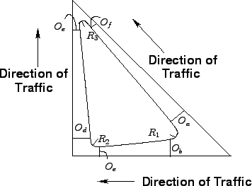
The orientation of islands near intersections is dictated by the alignment of
the intersecting roadways and their associated travel paths.
Proper island design must minimize the potential for vehicle impacts and reduce
their severity.
This is most often accomplished by offsetting the approach ends of islands from
the edge of travel lane them, tapering them inward.
Another technique that is the use of rounded approach noses that may also be
sloped downward on their approach ends.
The general design dimensions of corner islands for roadways in shown in
Fig. 1.
Figure 1:
Recommended Offset Dimensions for location of Traffic Islands
 |
Another design consideration for islands is their surface finishing.
Islands may be paved or landscaped.
Though paved islands are easier to maintain, yet they are typically not as
aesthetically pleasing.
The use of colors that have contrast with the pavement surface is desirable
because they allow the island to be more clearly seen by drivers.
Normally concrete islands are paired with asphalt roadways and vice versa.
Brick paver are also used in areas where aesthetics are important.
Other concerns include the need to provide adequate slope to the surface of the
island to facilitate drainage and to keep the island free of sight obstructions
and collision.
Thus, all landscaping features should be kept below the clear vision envelop and
should not incorporate other fixed hazards.
The combination of a simple radius flanked by tapers can often fit the pavement
edge more closely to the design motor vehicle than a simple radius (with no
tapers).
Figs. 2, 3 and
4 shows the various types of curves that can be used for
a roadway.
The closer fit can be important for large design motor vehicles where effective
pavement width is small (due either to narrow pavement or need to avoid any
encroachment), or where turning speeds greater than the design speed are
desired.
Figure 2:
Various types of curves used for a turning roadway , (a)Simple Radius
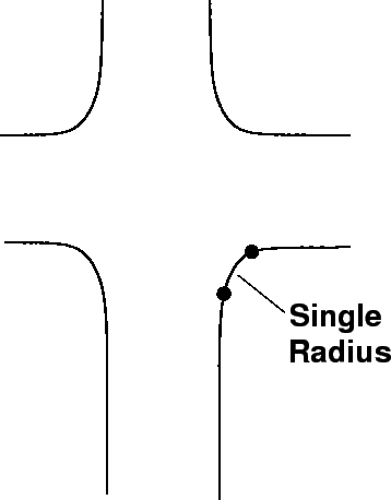 |
Figure 3:
Various types of curves used for a turning roadway, (b)Radius and Taper
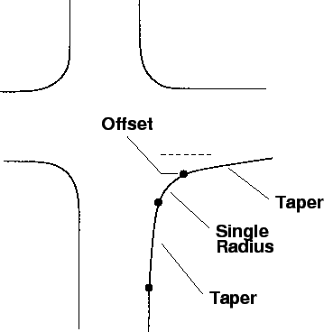 |
Figure 4:
Various types of curves used for a turning roadway, (c)Turning Roadway
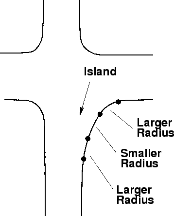 |
Table. 1 and Table. 2 summarizes
design elements for curve/taper combinations that permit various design motor
vehicles to turn, without any encroachment, from a single approach lane into a
single departure lane (Note: W should be determined using the turning path of
the design vehicle)
Table 1:
Curve and Taper Corner Design Elements
| Angle of Turn |
Design Vehicle |
Radius |
Offset |
Taper Length |
| (Degrees) |
|
(meters) |
(OS meters) |
(T1 meters) |
| |
Passenger Car |
7.5 |
0.6 |
6 |
| 75 |
Single Unit Truck |
13.5 |
0.6 |
6 |
| |
Single Trailer Unit |
19.5 |
0.9 |
13.5 |
| |
Passenger Car |
6 |
0.75 |
7.5 |
| 90 |
Single Unit Truck |
12 |
0.6 |
6 |
| |
Single Trailer Unit |
18 |
1.2 |
18 |
| |
Passenger Car |
6 |
0.6 |
- |
| 120 |
Single Unit Truck |
9 |
0.9 |
- |
| |
Single Trailer Unit |
13.5 |
1.2 |
18 |
Table 2:
Design elements for Turning Roadways
| Angle of Turn |
Design Vehicle |
Radius(meter) |
Offset |
| (Degrees) |
|
R1-R2-R1 |
(OS meter) |
| |
Passenger Car (P) |
30-22.5-30 |
0.6 |
| 75 |
Single Unit Truck (SU) |
36-13.5-36 |
0.6 |
| |
Semi-Trailer Unit (WB-50) |
45-15-45 |
2 |
| |
Passenger Car (P) |
30-6-30 |
0.8 |
| 90 |
Single Unit Truck (SU) |
36-12-36 |
0.6 |
| |
Semi-Trailer Unit (WB-50) |
54-18-54 |
2 |
| |
Passenger Car (P) |
30-6-30 |
0.6 |
| 120 |
Single Unit Truck (SU) |
30-9-30 |
0.9 |
| |
Semi-Trailer Unit (WB-50) |
54-12-54 |
2.6 |
The width of the roadway can be found out from Table. 3
given below.
Table 3:
Width of roadway required for negotiating the turn for different
classes of vehicles (W)
| Radius on |
One-Lane One Way |
One-Lane One Way |
Two way operation |
| inner edge |
Operation (No |
Operation
(Having |
Either One way or Two |
| of |
provision of passing a |
provision
of passing a |
way (Same Type of vehicle |
| pavement |
stalled vehicle) in meter |
stalled vehicle) in meter |
in both
lanes) in meter |
| in meter |
P |
SU |
WB-50 |
P |
SU |
WB-50 |
P |
SU |
WB-50 |
| 15 |
3.9 |
5.4 |
7.8 |
6 |
8.7 |
13.2 |
7.8 |
10.5 |
15 |
| 22.5 |
3.9 |
5.1 |
6.6 |
5.7 |
8.1 |
10.8 |
7.5 |
9.9 |
12.6 |
| 30 |
3.9 |
4.8 |
6.3 |
5.7 |
7.5 |
10.2 |
7.5 |
9.3 |
12 |
| 45 |
3.6 |
4.8 |
5.7 |
5.4 |
7.2 |
8.7 |
7.2 |
9 |
10.5 |
| 60 |
3.6 |
4.8 |
5.1 |
5.4 |
6.9 |
8.1 |
7.2 |
8.7 |
9.9 |
| 90 |
3.6 |
4.5 |
5.1 |
5.4 |
6.6 |
7.5 |
7.2 |
8.4 |
9.3 |
|
|
| | |
|
|
|