| |
| | |
|
Design of a channelized intersection usually involves the following significant
controls: the type of design vehicle, the cross sections on the crossroads, the
projected traffic volumes in relation to capacity, the number of pedestrians,
the speed of vehicles, and the type and location of traffic control devices.
Furthermore, the physical controls such as right-of-way and terrain have an
effect on the extent of Channelization that is economically feasible.
The degree to which each of these principles applies will depend upon the
features mentioned above.
While a principle may be modified in its application to a particular site,
disregard of these may result in a hazardous design.
The principles may be summarized as follows:
- Reduction of the Area of Conflict: The impact area is decreased
when Channelization is provided, and hence the probability of conflicts is also
reduced.
The figure below further clarifies the statement.
Fig. 1 shows the conflict area in a Y-intersection
without Channelization and Fig. 2 shows the
reduced conflict area in the same intersection after providing medians.
Figure 1:
Conflict area in all paved intersection
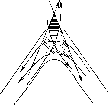 |
Figure 2:
Conflict area in a channelized intersection
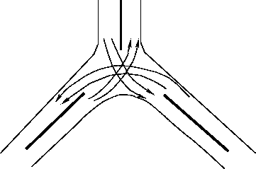 |
- Merging traffic streams at small angles: Merging at small angles
permits the flow of traffic streams with minimum speed differentials.
Hence, the gap acceptance time is also small in such cases.
The merging of roadways should be done as shown below in
Fig. 3.
Figure 3:
Merging of traffic streams
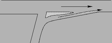 |
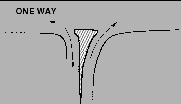
- Reduction of the speed of incoming traffic by bending its path:
The speed of vehicles entering into the intersection can be reduced by bending
the path to the intersection approach.
However as far as possible the path of the major traffic stream should not be
bent.
The above technique is shown below in Fig. 4.
Figure 4:
Bending path of incoming minor street
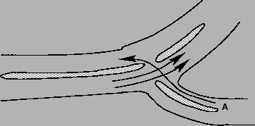 |
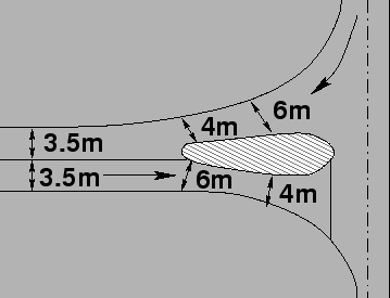
- Reduction of speed of traffic by funneling: The funneling
technique can also be used for reducing the speeds of the incoming vehicles.
Due to the decrease in the width of the lane at the approach, the drivers tend
to reduce the speed of their vehicles near the intersection.
Fig. 5 shows the funneling technique used for reduction
of speed.
Figure 5:
Reduction of speed by funneling
 |
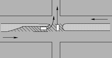
- Protection for turning vehicles/crossing conflicting traffic
streams: Provision of a refuge area between the two opposing streams allows the
driver of a crossing vehicle to select a safe gap in one stream at a time and
also provides a safer crossing maneuver.
Fig. 6further clarifies the above statement.
Figure 6:
Refuge area for protecting crossing or turning traffic
 |
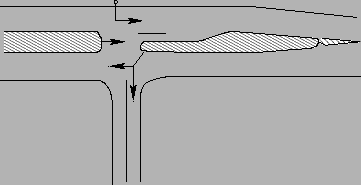
- Discourage prohibited turns by island placement and shape:
Undesirable and prohibited turns can be discouraged by the proper selection of
shape and location of the islands.
Fig. 7 shows how prohibited turns can be
discouraged by proper shaping and placement of islands.
Figure 7:
Properly placed islands discourage prohibited movements
 |
- Providing locations of traffic control devices: Channelization
may provide locations for the installation of essential traffic control devices,
such as stop and directional signs, signals etc.
Fig. 8 shows how channelizing devices can also be
used for locating traffic control devices.
Figure 8:
Location of signal posts on medians at intersections
 |
|
|
| | |
|
|
|