The nomenclature used in the fig.8.9 is described below
| Tha: Inlet temperature of hot fluid | |
| Thb: Outlet temperature of hot fluid | |
| Tca: Inlet temperature of cold fluid | |
| Tcb: Outlet temperature of cold fluid | |
| Tci: Intermediate temperature of cold fluid |
In the above arrangement it is assumed that the hot fluid is flowing in the shell side and cold fluid is flowing in the tube side of the exchangers. The fig.8.9 (a) shows the 1-2 exchangers in which the hot fluid enter into the exchanger from the left side and exits from the right side. The cold fluid enters concurrently that is from the left side to the tube of the exchangers and goes up to right end of the exchangers and returns back to make two tube pass, and exits from the left end of the exchangers. The temperature profile all along the length of the exchanger is shown in the corresponding temperature length profile. Figure8.9 (b) shows the flow direction and corresponding temperature length profile for 2-4 exchangers. The shell side fluid two passes and the tube side fluid has 4-passes in the exchangers.
It can be easily understood that whenever the number of passes is more than one, the flow cannot be truly co-current or counter current. Thus it will be a mix of co-current and counter current flows in any multi pass heat exchangers.
Though the temperature profile of the hot and cold streams can be easily predictable for single pass heat exchangers but for the complex flow modes, the prediction of temperature distribution will be difficult as shown in fig.8.9. As can be seen when 1-2 exchangers was (fig.8.9 (a)) used in co-current mode, the temperature profile was given in the figure. However, if the fluid streams enter in counter current mode a temperature cross may occur sometimes. Temperature cross is described as the positive temperature difference between the cold and the hot fluid, when these fluids leave the exchangers. In that case the cold fluid will attain the maximum temperature inside the exchanger instead of at the exit (fig.8.10).
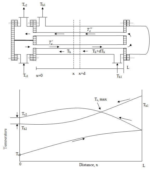
Fig. 8.10: 1-2 flow pattern and temperature profile in exchanger showing cross flow
At this temperature cross, the cold fluid temperature reaches the maximum at a point inside the exchanger and not at its exits. This temperature cross point also coincides with the point of intersection of the temperature profile of the hot fluid and the co-current zone of the cold fluid. The difference (Tc2 - Th2) is called the temperature cross of the exchanger. However, if the temperature cross does not appear then the (Tc2 - Th2) is called the approach. Moreover, on careful evaluation it can be seen that for the multi shell side pass a significant length of the exchanger have cross flow pattern in the tube flow when the shell side fluid is migrating from one shell pass to another shell pass. Thus calculating heat transfer co-efficient for shell side becomes little challenging and will be explained in section 8.2.6. Although the parallel flow or counter flow arequite similar, the parallel flow and counter flow heat exchangers differ greatly in the manner in which the fluid temperatures vary as the fluid pass through. The difference can be understood in the figure 8.11.