8.2 Thermal design of heat exchangers
The mechanical design is done by the mechanical engineers on the inputs of chemical engineers and using the codes. The most widely used code in Tubular Exchanger Manufactures Associations (TEMA). This USA code along with ASME selection VIII (unfired pressure vessel) code is used together for the mechanical design of the heat exchanger. The Indian code for the heat exchanger design IS 4503.
Here we would discuss about the process design (or thermal design) leading to the sizing of the heat exchanger. Before understanding design steps, it is necessary to understand the following for the heat exchanger.
8.2.1 Overall heat transfer coefficient
As understood by the previous discussion that generally heat exchangers are tubular in nature (Note: we are not discussing about plate type heat exchangers). Thus we can easily find out the overall heat transfer coefficient based on our previous knowledge. Figure 8.8 shows a simplest form (double pipe heat exchanger) of tubular heat exchanger, where fluid A is being heated by fluid B in a co-current flow pattern. The inside and outside radii of the inner tube is represented ri and ro. The length of the exchanger for heat transfer is considered as L for section 1 to 2.
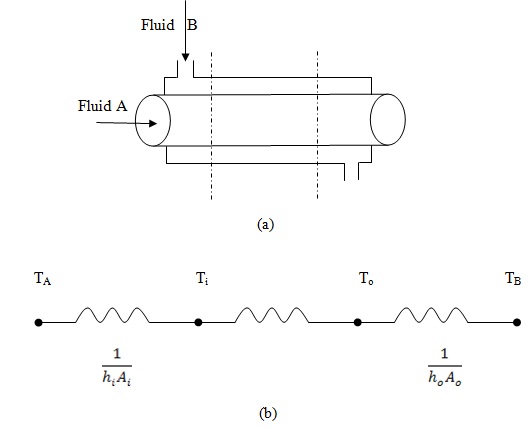
Fig.8.8: (a) Schematic of a double pipe heat exchanger (b) thermal resistance network for overall heat transfer
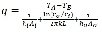
Thus the rate of heat transfer from the hot fluid to the cold fluid will be represented by eq.8.1,
|
(8.1) |
The overall heat transfer coefficient;
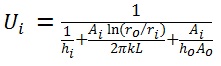
Based on inside area of the inner pipe (eq.8.2)
|
(8.2) |
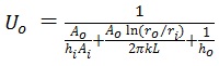
Based on outer side area of the outer pipe (eq.8.3)
|
(8.3) |