One fluid flows through the tubes while the other fluid flows around the outside of the tubes, it is the space between the tube sheets and enclosed by the outer shell.
For a thorough distribution of the shell side fluid, baffles are placed normal to the tube bundle. This baffle creates turbulence in the shell side fluid and enhances the transfer coefficients for the shell side flow.
Fig. 8.2 shows the simplified diagram of a shell and tube heat exchanger, showing a few of the important components. Infact, the present heat exchanger used in the process industry are quite complex and have improved design such as factors for thermal expansion stresses, tube fouling due to contaminated fluids, ease of assembly and disassembly, size, weight, etc.
The heat exchanger shows in fig. 8.2 is having one shell and one tube pass since both the shell and tube side fluid make a single traverse through the heat exchanger. Thus, this type of shell-and-tube heat exchangers is designated as 1-1 exchanger. If we desire to pass the tube fluid twice, then it is designated as 1-2 exchangers. Similarly, if there are 2 shell pass and 4 tube pass, the designation will be 2-4 exchanger. The number of pass in tube side is done by the pass partition plate. A pass particular plate or pass divider as shown in fig.8.5. The shell side pass can be creator by a flat plate as shown in fig.8.6.
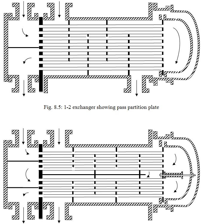
Fig. 8.6: 2-4 exchanger showing shell and tube passes
It can be understood that for a given number of tubes; the area available for flow of the tube side fluid is inversely proportional to the number of passes. Thus, on increasing the pass the area reduces and as a result the velocity of fluid in the tube increases and henceforth the Reynolds number increases. It would result in increased heat transfer coefficient but at the expense of high pressure drop. Generally, even numbers of tube passes are used for the multi-pass heat exchangers.