The heat exchanger as shown in fig. 8.2 consists of a bundle of tubes properly secured at either ends in tube sheets. The tube sheets are drilled plates into which the tubes are fixed up using different technique to have leak proof joints. The entire tube bundles shown in the fig. 8.3 is placed inside a closed shell, which seals around the tube sheet periphery to form the two immiscible zones for hot and cold fluids are shown in fig.8.4.
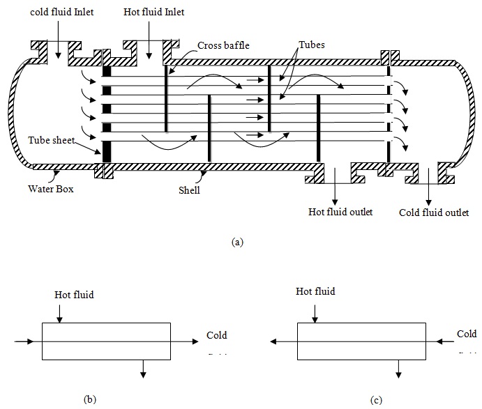
Fig.8.2: A schematic of (a) one-shell pass, one tube pass heat exchanger; (b) parallel flow; and (c) counter flow
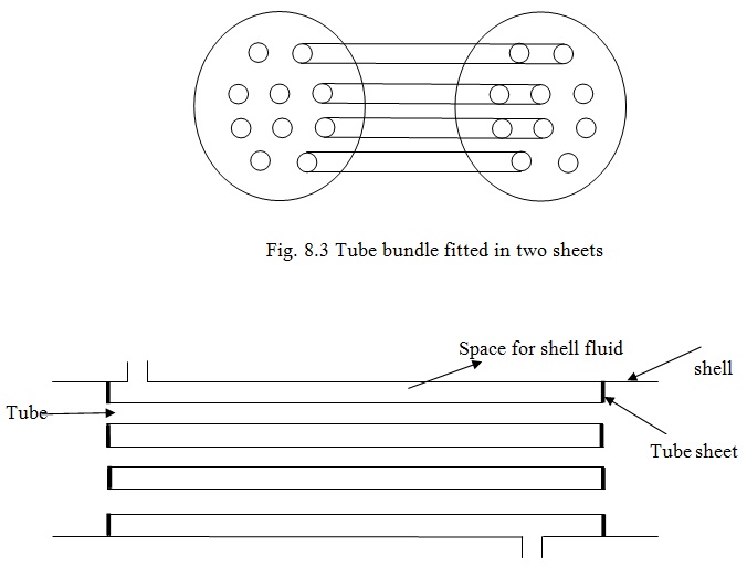
Fig. 8.4: Tube bundle inside a shell