Deactivation
The major sources of catalyst deactivation are
- 1. Coke formation
2. Deactivation by metals such as Ni, V
3. Sintering
Coke formation on the catalyst surface is the major deactivation source for catalytic cracking catalysts. Very high rate of coke formation results in very low residence time of catalysts in the reactor and high regeneration frequency. The metal residue in the feed can also affect the performance and activity of the catalysts. Nickel increases gas and coke selectivities while vanadium is reported to destroy zeolites and lowers the activity. The effects of metals can be prevented by adding metal passivators. Antimony or bismuth compound can be added which form Ni-Sb or Ni- Bi alloy. Magnesium orthosilicate is also added to form MgO-V2O5-SiO2. At severe conditions of high temperature and steam, zeolite structure gradually deteriorates.
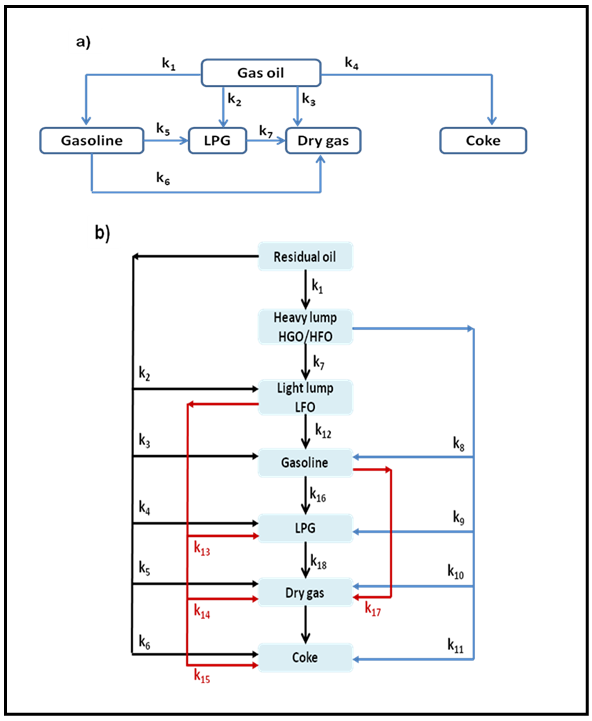
Fig. 5. Lump kinetic models for catalytic cracking (a) Five lump kinetic models [4] (b) seven lump kinetic models [5]
Hydrocracking
This process has wide range of applications including upgradation of petrochemical feedstock, improvement of gasoline octane number, production of high quality lubricants etc. The process upgrades the original feedstock by increasing its overall hydrogen-to-carbon ratio and decreasing the average molecular weight.
Hydrocracking is extensively used for simultaneously cracking and hydrogenating low value gas oil, containing high amount of cyclic polyaromatic and naphthenic compounds, to produce high value products such as gasoline, diesel or jet fuel. Hydrocracking involves multiple reactions such as ring opening, cracking, dealkylation and isomerization with simultaneous saturation due to presence of hydrogen. The major advantage of this process is higher selectivity towards cracking of polyaromatics to desired fuels such as gasoline, diesel or jet fuel and less production of lower hydrocarbons. This is in contrast with catalytic cracking process which gives rise to considerable amount of lower alkene products. Some of the typical reactions are shown in Fig. 6.
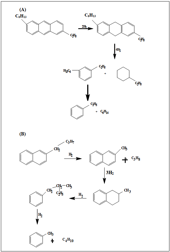
Fig. 6. Typical hydrocracking reactions