Catalyst
Common cracking catalysts are amorphous SiO2-Al2O3 and zeolites. Zeolites are alumino-silicates with well- defined crystalline structures having molecular size pores that give rise to its shape selective properties. Zeolites are discussed in detail in later sections. The product distribution in catalytic cracking process also depends on the type of catalyst. The SiO2-Al2O3 catalyst gives higher alkene yield while zeolite catalyst result in higher aromatic yield.
The typical commercial cracking catalyst is a mixture of zeolite and SiO2–Al2O3. The catalyst can contain 3-25 wt.% zeoliteY. The zeolite is usually ion exchanged with rare earth ions such as La+3 or Ce+3 to provide additional thermal stability. The balance of mixture is SiO2 -Al2O3, similar to the original amorphous cracking catalyst. The function of acidic SiO2 -Al2O3 is to crack the large feed molecules to a size which can diffuse into the zeolite channels for further reactions. The alumino-silicate matrix also protects the zeolite from poisons and attrition. The catalyst particles are of 40-100 µm in diameter with pore sizes in the range of 8-10 nm. Surface area of the zeolite ranges from 600-800 m2/g, whereas, the surface area of the alumino-silicate matrix is in the range of 100-300 m2/g.
Additives are added to cracking catalyst and constitute about 5 wt. % of catalyst. Commonly used additives include octane boosting additives such as ZSM-5, metal passivators, SOx reducing agents, and CO oxidation catalyst. Addition of 1-3 wt. % of ZSM-5 increases octane number while decreases gasoline yield. Nickel increases gas and coke selectivities while vanadium destroys the zeolite lowering the activity. These undesirable effects of Ni can be minimized by adding a passivator such as a compound of antimony and bismuth to the process stream to react selectively with the Ni to form a catalytically inactive Ni-Sb or Ni-Bi species. These are added commonly as organometallic solutions to the process stream.
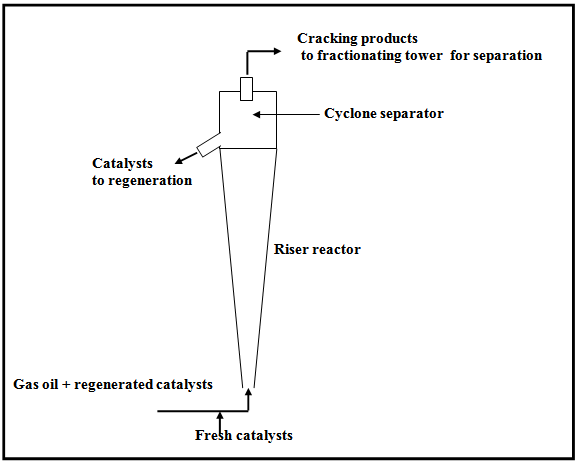
Fig. 3. Schematic diagram for catalytic cracking in Riser reactor.
Mechanism and kinetics
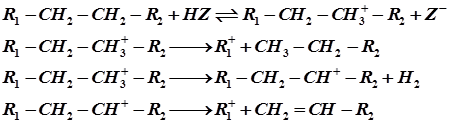
Cracking reactions involve C-C bond rupture via formation of carbocations. Reaction is catalyzed by acid sites on SiO2–Al2O3 and zeolites catalysts. Carbocations are formed on Bronsted and Lewis acid sites of the catalysts. A typical mechanism for catalytic cracking of alkane initiated by protonation is given below:
A detailed micro kinetic model for gas oil cracking involve hundreds of elementary reaction steps for which kinetic parameters are to be determined. Due to this complexity of cracking process, the kinetic study of these reactions is extremely difficult. For simplification, the reaction steps and products are combined into groups of species. These groups are called lumps and each lump is considered as an independent entity. This is known as lumped kinetic technique.
A three lumped model proposed by Wojciechowski and Corma [3] for gas oil cracking is shown in Fig. 4. Simple parallel- series kinetic network involves reactions of gas oil to gasoline /diesel (path 1) or to gases/coke (path 2). The gasoline and diesel can further react to give gas and coke.
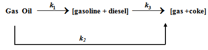
Fig. 4. Three Lumped kinetic model for catalytic cracking of gas oil
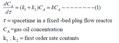
The corresponding reaction kinetics was proposed to be first order with respect to each hydrocarbon component of the feed reacting by path 1 or 2.
To account for rapid catalyst decay, each of the rate constants was modified using a time–on-stream functions:
![]()
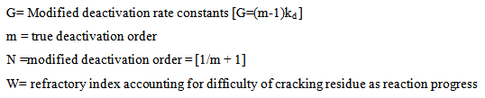
Upon substituting the modified rate constants for k1 and k2 into equations (1) and inserting this expression in equation for plug flow and integrating, an expression was obtained by Wojciechowski and Corma [3] which relates instantaneous conversion XA to the time of reaction tf while accounting for volume expansion εA.
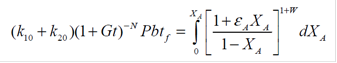
b = constant and P= catalyst to oil ratio
This above model although useful for modeling the kinetics of gas oil cracking, was highly empirical and could not be generalized for kinetics of catalytic cracking.
A five lump kinetic model (Fig 5a) was proposed to describe the gas oil catalytic cracking (FCC) process by Ancheyta-Juárez et al.[4]. The model contained eight kinetic constants, including one for catalyst deactivation. The model included unconverted gas oil, gasoline, LPG, dry gas and coke as lumps. The activation energies of the various steps were in the range of 9-13 kcal/mol. Even seven lump kinetic models for fluid catalytic cracking, as shown in Fig. 5b, are reported in literature. The shown seven-lump model involved residual oil, heavy lump, light lump, gasoline, liquefied petroleum gas, dry gas and coke [5]. The VGO, HFO and LFO in Fig 5b are vacuum gas oil, heavy fuel oil and light fuel oil respectively.