Shock Tunnel: It consists of two major parts, the shock tube and the wind tunnel portion. The general schematic layout of the shock tunnel, consisting of shock tube and wind tunnel section, is shown in Fig. 8.2.3. The shock tube portion consists of a constant area tube separated by a diaphragm (generally, metal) into regions of high and low pressures. High and low pressure regions are called ‘driver tube' and ‘driven tube' respectively. The shock tube works on the principle of using a high-pressure gas in the driver tube to set up a shock wave, which propagates into the low pressure gas in the driven tube at the instant of diaphragm rupture. The propagating shock wave compresses and heats the low-pressure test gas in the driven tube to a high pressure and temperature, and also imparts the test gas a high kinetic energy, with which it starts moving at a supersonic Mach number behind the propagating shock wave. This shock wave ideally travels through the driven section at a constant velocity, and there exists a region of steady supersonic flow of high temperature and pressure between the moving driver/driven gas interface and the shock wave.
The wind tunnel portion of the shock tunnel consists of a hypersonic nozzle that is attached to the driven end of the shock tube, a test section at the exit of the nozzle where the measurements are carried out, and a dump tank portion to accommodate the gas. The shocked high pressure/temperature gas from the shock tube is then expanded through the hypersonic nozzle to the desired Mach number and velocity in the tunnel test section. The ability of the shock tube portion of the hypersonic shock tunnel to heat the test gas to the conditions encountered in hypersonic flight makes it an attractive tool for hypersonic flow research. The test flow duration in a shock tunnel is in the range of 1ms.
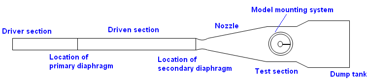
Fig. 8.2.3: Schematic representation of a shock tunnel.