High Speed Wind Tunnel
Experimental facilities for supersonic and hypersonic flow regimes are different from those used at subsonic speeds. In supersonic flows, the interest lies in simulating flow Reynolds number and the Mach numbers in the test section of the tunnel. In addition to these parameters, the total energy content (i.e. enthalpy) of the flow also becomes important at hypersonic speeds. The wind tunnels used in the Mach number range 1 to 5 are called as supersonic tunnels while the tunnels used for higher Mach numbers (> 5) are called as hypersonic tunnels.
The high speed tunnels can be of open/closed circuit type. The open circuit wind tunnel takes the air from atmosphere and rejects them to a vacuum chamber. In contrast, the same air is re-circulated in a closed circuit wind tunnel. In the case of subsonic wind tunnels, experiments can be performed by running the tunnel continuously. But, when the velocity of air in the test section increases, the power requirement becomes very high because it is proportional to the cube of the velocity. Thus, in many cases, it is preferred to run high speed wind tunnels for a short duration and gather all the experimental data in this short time period (~1-5s). So, such types of tunnels are called as blow down tunnels. These tunnels operate intermittently using high pressure tanks and/or vacuum tanks.
Blow down wind Tunnel (Open circuit type)
The high pressure chamber, vacuum section, nozzle and test section are few important components of a blow down wind tunnel. The schematic diagram is shown in Fig. 8.2.1. Since, the air from the high pressure chamber flows towards the vacuum section, it is referred as pressure-vacuum tunnel. First, the air is taken from the atmosphere and after compression; it is stored in a tank. Simultaneously, the low pressure section is evacuated by a vacuum pump. Pressure regulator controls the air flow from reservoir to the settling chamber during the actual experiment and maintains the desired constant pressure. The nozzle expands the flow by increasing velocity and decreasing pressure and provides desired Mach number in the test section. The high speed air encounters deceleration while passing through the second throat.
These blow down tunnels are inherent intermittent tunnels but bear many advantages over continuous wind tunnels such as high Mach capability (up to 4), easy tunnel starting, large size test section, lower construction/operating costs, superior design for propulsion experiments and smoke visualization. The limitations of the blow down tunnels are requirement of faster data acquisition system, noisy operation and necessity of pressure regulator valves. The blow down tunnel can be of different types based on the driving pressure difference is achieved. In one such tunnel, air expands from high pressure to the atmospheric pressure where low pressure chamber is excluded (intermittent blow down tunnel). In other cases, the atmospheric air can expand up to a very low vacuum (intermittent in-draft wind tunnel). Depending on the requirement of Mach number in the test section, the tunnel is chosen accordingly.
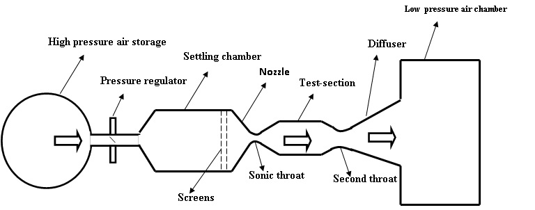
Fig. 8.2.1: Schematic diagram of a blow down wind tunnel (open circuit)