Here, ![]() is geometrically normal to the surface and
is geometrically normal to the surface and ![]() is tangential to the surface of the cylinder as shown in Fig. 3.7.2(a). The negative sign signifies that
is tangential to the surface of the cylinder as shown in Fig. 3.7.2(a). The negative sign signifies that ![]() is positive in the direction of increasing θ. It may be observed that the velocity at the surface reaches to maximum value of
is positive in the direction of increasing θ. It may be observed that the velocity at the surface reaches to maximum value of ![]() at the top and bottom of the cylinder as shown in Fig. 3.7.2(b). Eqs. (3.7.6) and (3.7.7) can be combined to obtain the surface pressure coefficient as,
at the top and bottom of the cylinder as shown in Fig. 3.7.2(b). Eqs. (3.7.6) and (3.7.7) can be combined to obtain the surface pressure coefficient as,
|
(3.7.8) |
The pressure distribution over the cylinder is plotted in Fig. 3.7.3. Here, ![]() varies from 1 at the stagnation point to -3 at the points of maximum velocity. It is also clear that the pressure distribution at the top half the cylinder is equal to the bottom half and hence the lift is zero. Similarly, the pressure distribution on the front part of the cylinder is exactly balanced by rear portion and there is no drag. Both, normal force and axial force coefficients
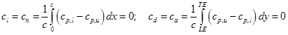
varies from 1 at the stagnation point to -3 at the points of maximum velocity. It is also clear that the pressure distribution at the top half the cylinder is equal to the bottom half and hence the lift is zero. Similarly, the pressure distribution on the front part of the cylinder is exactly balanced by rear portion and there is no drag. Both, normal force and axial force coefficients ![]() are same as lift and drag coefficients. They are calculated from
are same as lift and drag coefficients. They are calculated from ![]() as given below;
as given below;
 |
(3.7.9) |
Here, LE and TE stands for leading edge and trailing edge, respectively. The subscripts u and l refers to upper and lower surface of the cylinder. The chord c is the diameter of the cylinder (R).
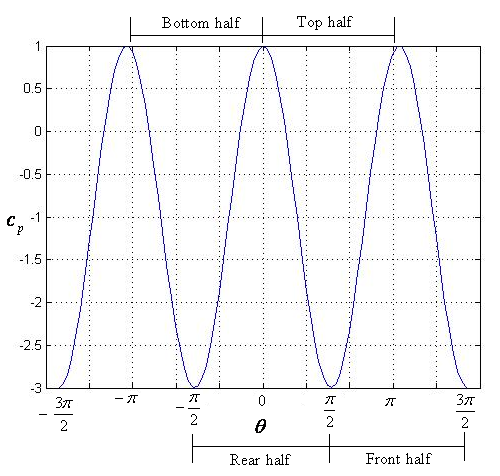
Fig. 3.7.3: Surface pressure coefficient for a circular cylinder.
When the surface pressure matches with free stream pressure, then Eq. (3.7.8) reduces to,
|
(3.7.10) |
These points as well as the stagnation points and location of minimum pressure are illustrated in Fig. 3.7.4.
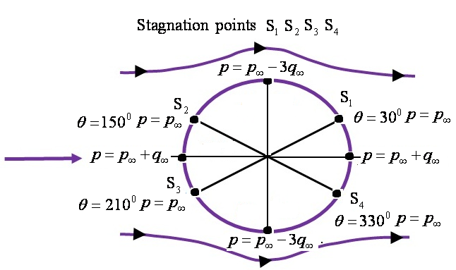
Fig. 3.7.4: Pressure values at various locations on the surface of the cylinder.