Visualization of Fluid Flow
The quantitative and qualitative information of fluid flow can be obtained through sketches, photographs, graphical representation and mathematical analysis. However, the visual representation of flow fields is very important in modeling the flow phenomena. In general, there are four basic types of line patterns used to visualize the flow such as timeline, pathline, streakline and streamlines. Regardless of how the results are obtained, (i.e. analytically/experimentally/computationally) it is necessary to plot the data to get the feel of flow parameters that vary in time and/or shape (such as profile plots, vector plots and contour plots).
(a) Timeline: A ‘timeline' is a set of fluid particles that form a line at a given instant (Fig. 3.1.1-a). Thus, it is marked at same instant of time. Subsequent observations of the line provide the information of the flow field. They are particularly useful in situations where uniformity of flow is to be examined.
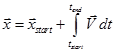
(b) Pathline: It is the actual path traversed by a given fluid particle as it flows from one point to another (Fig. 3.1.1-b). Thus, the pathline is a Lagrangian concept that can be produced in the laboratory by marking the fluid particle and taking time exposure photograph of its motion. Pathlines can be calculated numerically for a known velocity field ![]() i.e.
i.e.
 |
(3.1.7) |
(c) Streakline: A streakline consists of all particles in a flow that has previously passed through a common point (Fig. 3.1.1-c). Here, the attention is focused to a fixed point in space (i.e. Eulerian approach) and identifying all fluid particles passing through that point. These lines are laboratory tool rather than analytical tool. They are obtained by taking instantaneous photographs of selected particles that have passed through a given location in the flow field.
(d) Streamline: These are the lines drawn in the flow field so that at a given instant, they are tangent to the direction of flow at every point in the flow field (Fig. 3.1.1-d). Since the streamlines are tangent to the velocity vector at every point in the flow field, there can be no flow across a streamline. Mathematically, these lines are obtained analytically by integrating the equations defining lines tangent to the velocity field. In a two dimensional flow field as shown in the figure, the slope of the streamline is equal to the tangent of the angle that velocity vector makes with x- axis i.e.
(3.1.8) |