Voltage Divider Bias:
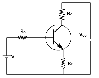
If the load resistance RC is very small, e.g. in a transformer coupled circuit, then there is no improvement in stabilization in the collector to base bias circuit over fixed bias circuit. A circuit which can be used even if there is no dc resistance in series with the collector, is the voltage divider bias or self bias. fig. 3.
The current in the resistance RE in the emitter lead causes a voltage drop which is in the direction to reverse bias the emitter junction. Since this junction must be forward biased, the base voltage is obtained from the supply through R1, R2 network. If Rb = R1 || R2 equivalent resistance is very very small, then VBE voltage is independent of ICO and ¶ IC / ¶ ICO ® 0. For best stability R1 & R2 must be kept small.
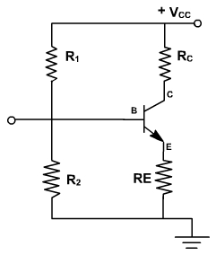
Fig. 3
If IC tends to increase, because of ICO, then the current in RC increases, hence base current is decreased because of more reverse biasing and it reduces IC .
To analysis this circuit, the base circuit is replaced by its thevenin's equivalent as shown in fig. 4.
Fig. 4
Thevenin's voltage is
Rb is the effective resistance seen back from the base terminal.
If VBE is considered to be independent of IC, then

The smaller the value of Rb, the better is the stabilization but S cannot be reduced be unity.
Hence IC always increases more than ICO. If Rb is reduced, then current drawn from the supply increases. Also if RE is increased then to operate at same Q-point, the magnitude of VCC must be increased. In both the cases the power loss increased and reduced h.
In order to avoid the loss of ac signal because of the feedback caused by RE, this resistance is often by passed by a large capacitance (> 10 m F) so that its reactance at the frequency under consideration is very small.