Emitter Feedback Bias:
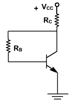
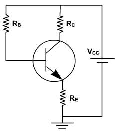
Fig. 1, shows the emitter feedback bias circuit. In this circuit, the voltage across resistor RE is used to offset the changes in bdc. If bdc increases, the collector current increases. This increases the emitter voltage which decrease the voltage across base resistor and reduces base current. The reduced base current result in less collector current, which partially offsets the original increase in bdc. The feedback term is used because output current ( IC) produces a change in input current ( IB ). RE is common in input and output circuits.
Fig. 1
In this case

Since IE = IC + IB
Therefore,
In this case, S is less compared to fixed bias circuit. Thus the stability of the Q point is better.
Further,
If IC is to be made insensitive to βdc than
RE cannot be made large enough to swamp out the effects of βdc without saturating the transistor.
Collector Feedback Bias:
In this case, the base resistor is returned back to collector as shown in fig. 2. If temperature increases. βdc increases. This produces more collectors current. As IC increases, collector emitter voltage decreases. It means less voltage across RB and causes a decrease in base current this decreasing IC, and compensating the effect of bdc.
Fig. 2
In this circuit, the voltage equation is given by

Circuit is stiff sensitive to changes in βdc. The advantage is only two resistors are used.
Then,
Therefore,
It is better as compared to fixed bias circuit.
Further,
Circuit is still sensitive to changes in βdc. The advantage is only two resistors are used.