Oscillators:
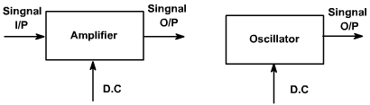
An oscillator may be described as a source of alternating voltage. It is different than amplifier.
An amplifier delivers an output signal whose waveform corresponds to the input signal but whose power level is higher. The additional power content in the output signal is supplied by the DC power source used to bias the active device.
The amplifier can therefore be described as an energy converter, it accepts energy from the DC power supply and converts it to energy at the signal frequency. The process of energy conversion is controlled by the input signal, Thus if there is no input signal, no energy conversion takes place and there is no output signal.
The oscillator, on the other hand, requires no external signal to initiate or maintain the energy conversion process. Instead an output signals is produced as long as source of DC power is connected. Fig. 1, shows the block diagram of an amplifier and an oscillator.
Fig. 1
Oscillators may be classified in terms of their output waveform, frequency range, components, or circuit configuration.
If the output waveform is sinusoidal, it is called harmonic oscillator otherwise it is called relaxation oscillator, which include square, triangular and saw tooth waveforms.
Oscillators employ both active and passive components. The active components provide energy conversion mechanism. Typical active devices are transistor, FET etc.
Passive components normally determine the frequency of oscillation. They also influence stability, which is a measure of the change in output frequency (drift) with time, temperature or other factors. Passive devices may include resistors, inductors, capacitors, transformers, and resonant crystals.
Capacitors used in oscillators circuits should be of high quality. Because of low losses and excellent stability, silver mica or ceramic capacitors are generally preferred.
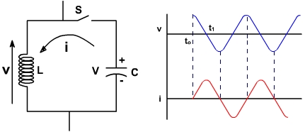
An elementary sinusoidal oscillator is shown in fig. 2. The inductor and capacitors are reactive elements i.e. they are capable of storing energy. The capacitor stores energy in its electric field.Whenever there is voltage across its plates,and the inductor stores energy in its magnetic field whenever current flows through it. Both C and L are assumed to be loss less. Energy can be introduced into the circuit by charging the capacitor with a voltage V as shown in fig. 2. As long as the switch S is open, C cannot discharge and so i=0 and V=0.
Fig. 2
Now S is closed at t = to, This means V rises from 0 to V, Just before closing inductor current was zero and inductor current cannot be changed instantaneously. Current increases from zero value sinusoidally and is given by
The capacitor losses its charge and energy is simply transferred from capacitor to inductor magnetic field. The total energy is still same. At t = t1, all the charge has been removed from the capacitor plates and voltage reduces to zero and at current reaches to its maximum value. The current for t> t1 charges C in the opposite direction and current decreases. Thus LC oscillation takes places. Both voltage and current are sinusoidal though no sinusoidal input was applied. The frequency of oscillation is